Vehicle drive apparatus

a technology of drive apparatus and drive shaft, which is applied in mechanical devices, gearing details, transportation and packaging, etc., can solve the problems of reducing the amount of oil pump discharge, increasing the drive loss of the oil pump, etc., and achieve the effect of reducing or preventing an increase in oil agitation

Active Publication Date: 2021-11-18
AISIN CORP
View PDF11 Cites 0 Cited by
  • Summary
  • Abstract
  • Description
  • Claims
  • Application Information

AI Technical Summary

Benefits of technology

[0015]This structure includes the oil guide. Thus, oil flowing toward the transmission through the return oil hole defined in the intermediate wall of the case is returnable to the oil reservoir through a region other than the chain placement region (i.e., through a region where no chain is placed). Accordingly, if the chain drive is disposed adjacent to the intermediate wall provided inside the case, this structure would reduce the amount of oil that enters the chain placement region of the chain drive after having reached a location toward the oil reservoir through the return oil hole. Consequently, this structure is able to reduce or prevent an increase in oil agitation caused by the chain.

Problems solved by technology

This unfortunately increases the drive loss of the oil pump and / or produces minute air bubbles in the oil, resulting in a reduction in the amount of discharge from the oil pump.

Method used


Image

  • Vehicle drive apparatus
  • Vehicle drive apparatus
  • Vehicle drive apparatus

Examples


first embodiment

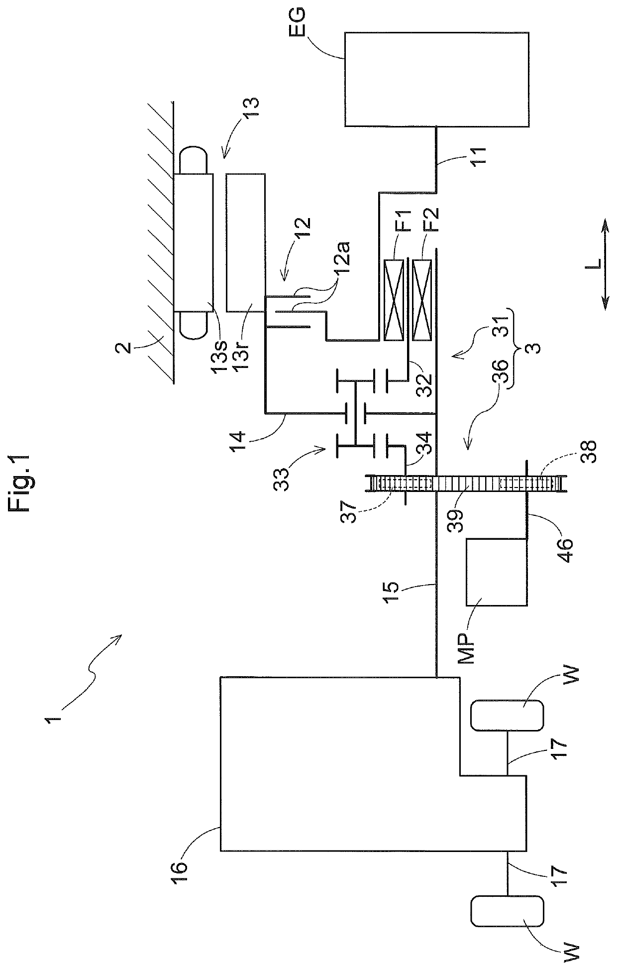
[0028]A vehicle drive apparatus according to a first embodiment will be described with reference to the drawings. The vehicle drive apparatus 1 according to the present embodiment is an apparatus for driving a hybrid vehicle (hereinafter referred to as a “hybrid vehicle drive apparatus”). The hybrid vehicle drive apparatus includes both of an internal combustion engine EG and a rotary electric machine 13 each functioning as a driving force source for wheels W. The vehicle drive apparatus 1 transmits a torque (which is generated by at least one of the internal combustion engine EG and the rotary electric machine 13) to the wheels W so as to cause a vehicle to travel. The vehicle drive apparatus 1 according to the present embodiment is provided in the form of an apparatus for driving a front-engine front-drive (FF) vehicle.

[0029]As illustrated in FIG. 1, the vehicle drive apparatus 1 includes: an input member 11 drivingly connected to the internal combustion engine EG; a friction enga...

second embodiment

[0064]A vehicle drive apparatus according to a second embodiment will be described with reference to the drawings. The second embodiment differs from the first embodiment in that the vehicle drive apparatus 1 according to the second embodiment includes no chain cover 6. Accordingly, the specific structures of the intermediate wall 22 and the support member 5 in the second embodiment are different from those in the first embodiment. The following description focuses mainly on the differences between the vehicle drive apparatus 1 according to the second embodiment and the vehicle drive apparatus 1 according to the first embodiment. Unless otherwise specified, elements similar to those of the first embodiment will be identified by the same reference signs and will not be described in detail.

[0065]As illustrated in FIGS. 8 to 10, the intermediate wall 22 of the case 2 of the vehicle drive apparatus 1 according to the present embodiment is provided with a gutter 23 and a rib 24. The gutt...


PUM


Abstract

An intermediate wall is provided with a return oil hole through which oil discharged from a friction engagement device returns toward an oil reservoir. A chain drive is disposed adjacent to the intermediate wall. The chain drive transmits a driving force from an input member and / or a rotary electric machine to an oil pump. There is provided an oil guide through which oil flowing through the return oil hole is guided to a region other than a chain placement region inside a case. The chain placement region is a region where a chain of the chain drive is placed.

Description

TECHNICAL FIELD[0001]The present disclosure relates to vehicle drive apparatuses.BACKGROUND ART[0002]A vehicle drive apparatus that has been in use includes: an input member drivingly connected to an internal combustion engine; output members drivingly connected to wheels; a friction engagement device; a rotary electric machine; a transmission; and a case housing the input member, the output members, the friction engagement device, the rotary electric machine, and the transmission. An example of such a vehicle drive apparatus is disclosed in WO 2016 / 136356 (Patent Document 1). The vehicle drive apparatus disclosed in Patent Document 1 includes an oil pump that is driven by a driving force from at least one of the internal combustion engine and the rotary electric machine through a chain drive. The chain drive is disposed between the friction engagement device and the transmission and between the rotary electric machine and the transmission in an axial direction.[0003]This structure ...

Claims


Application Information

Patent Timeline
Patent Type & Authority Applications(United States)
IPC IPC(8): F16H57/04F16H57/031
CPCF16H57/0424F16H57/0436F16H57/045F16H2057/02034F16H57/0409F16H57/031F16H57/0473B60K6/48F16H57/05B60K6/40F16H57/0441F16H2200/2064F16H2200/2094F16H57/0435F16H57/0476F16H2057/0216F16H57/0423B60K2006/4825B60K6/383Y02T10/62F16H57/0461
Inventor TORII, TAKAHIROKOJIMA, KAZUKIITO, MASAHIROISHIHARA, YUYA
Owner AISIN CORP
Why Eureka
Try Eureka