Flow control valve with eddy current dampening

Active Publication Date: 2019-04-09
ELEKTRONIK
View PDF7 Cites 6 Cited by
  • Summary
  • Abstract
  • Description
  • Claims
  • Application Information

AI Technical Summary

Benefits of technology

The present invention describes a valve designed to regulate the flow of particulate media. The valve has an inlet portion with repelling magnets and a shield to reduce the magnetic field. The inlet portion has a shuttle sleeve with shuttle magnets and a magnetic shield to reduce the magnetic field. The valve has a movable shuttle with a movable orifice attached to it that contacts a flow director. The valve is made from a metal that interacts with the shuttle magnets to generate eddy currents. The eddy currents act to dampen the movement of the shuttle. The technical effect of this design is the ability to regulate the flow of particulate media with a valve that reduces the likelihood of blockages and can adjust its flow direction to ensure consistent and accurate dispensing of the media.

Problems solved by technology

Existing flowable particulate valves in the art suffer from complexity, manufacturability, and functionality issues.
The pintle is spring-loaded to bias it towards the closed position, creating issues for assembly and maintenance.
The spring can wear, break, or become damaged, creating functionality issues.
When actuated, the pintle can bounce, creating control problems.
Another problem is having closed loop control of the valve by knowing exactly the amount of media that is being dispensed.

Method used


Image

  • Flow control valve with eddy current dampening
  • Flow control valve with eddy current dampening
  • Flow control valve with eddy current dampening

Examples


Embodiment Construction

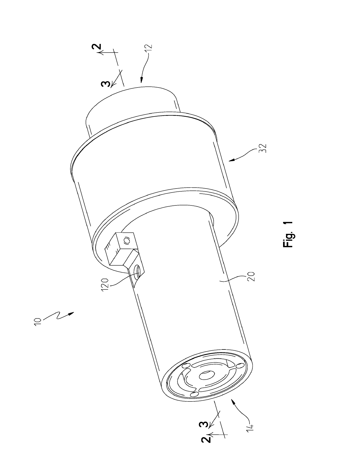
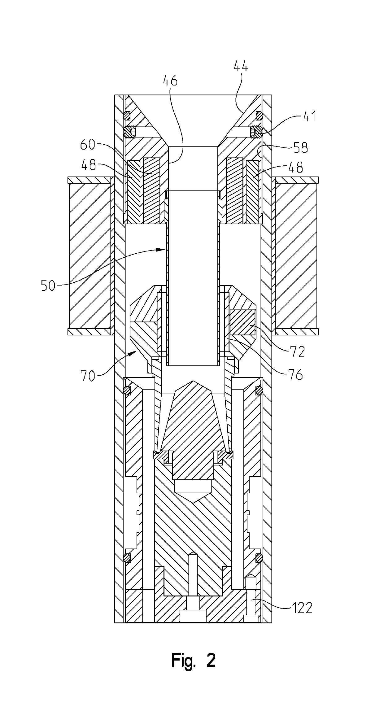
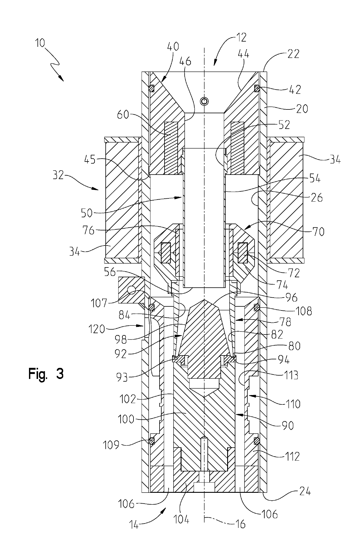
[0013]An electrically operated valve 10 is shown in FIGS. 1-8 with an inlet 12 and an outlet 14. The valve 10 is designed to regulate the flow of particulate media that is not ferro-magnetic. The particulate media is flowable, commonly a blasting media such as glass, plastic, aluminum oxide, or other particulate. In other words, particulate media made from steel or alloys of Iron are not commonly used with the valve 10. The particulate media is loaded into the inlet 12, commonly from a hopper or other storage vessel (not shown). The valve 10 is operable between an opened state and a closed state. The opened state allows particulate media to flow from the inlet 12 to the outlet 14, while the closed state blocks the particulate media from flowing. The valve 10 can operate in positions between the open and closed positions in order to regulate the flow of particulate media.

[0014]The valve 10 has a tube 20 that is shown as a hollow cylindrical tube with a consistent wall thickness, but ...


PUM


Abstract

A valve is provided having an inlet to receive a flowable particulate media and an outlet to dispense the media. The valve has an inlet portion with a funnel and repelling magnets. A shuttle sleeve extends from the inlet portion to allow a shuttle to slide along a central axis between an opened and a closed position. The shuttle has shuttle magnets that are oriented to have poles that face the repelling magnets to create a biasing force that biases the shuttle towards the closed position. When the shuttle moves, the shuttle magnets create eddy currents in a tube. The closed position is defined by a sealing edge of the shuttle contacting a sealing surface on a flow director. A capacitive sensor surrounds the flow director to measure the amount of media that is dispensed by the valve.

Description

BACKGROUND OF THE INVENTION[0001]This present disclosure relates to flow control valves that control the flow of particulate, such as is used in media blasting, shot peening, or other systems where the user desires to control the flow of different types of flowable particulate and sense the amount passing through the valve. Existing flowable particulate valves in the art suffer from complexity, manufacturability, and functionality issues. Most valves use a fixed orifice and a movable pintle that retracts to allow media to flow. The pintle is spring-loaded to bias it towards the closed position, creating issues for assembly and maintenance. The spring can wear, break, or become damaged, creating functionality issues. When actuated, the pintle can bounce, creating control problems. Another problem is having closed loop control of the valve by knowing exactly the amount of media that is being dispensed. Other designs use a deflected beam as a means to measure, while others use optical ...

Claims


Application Information

Patent Timeline
IPC IPC(8): F16K31/06F16K1/12F16K3/26F16K31/08F16K31/10F16K27/04F16K3/24B24C7/00
CPCF16K27/048F16K31/0668F16K31/10F16K3/265F16K31/0651F16K31/086F16K31/082F16K3/246F16K3/267F16K1/123B24C7/00Y10T137/3367F16K1/32F16K27/029F16K31/0655F16K31/0675F16K37/0091F16K47/00F16K37/005
Inventor CHAMPAIGNE, JACK M.
Owner ELEKTRONIK
Why Eureka
Try Eureka