
Running gear for a rail vehicle

a running gear and rail vehicle technology, applied in tramway vehicles, electric motor propulsion transmissions, railway components, etc., can solve the problems of unfavorable running behavior and unfavorable and achieve the effect of improving running behavior and improving dynamic properties of running gear

Active Publication Date: 2019-04-16
BOMBARDIER TRANSPORTATION GMBH
View PDF8 Cites 1 Cited by
  • Summary
  • Abstract
  • Description
  • Claims
  • Application Information

AI Technical Summary

Benefits of technology

[0004]Thus, it is the object of the present invention to provide an arrangement, which does not show the disadvantages described above, or at least shows them to a lesser extent, and which, in particular, provides, in a simple manner, improved running behavior and improved dynamic properties of the running gear of a rail vehicle.

Problems solved by technology

However, such running gears typically experience the disadvantage that, due to the lateral offset of the support location with respect to the running gear center, the reaction force (generating the reaction moment) acting on the running gear frame causes a rolling moment acting on the running gear frame about a rolling axis parallel to the longitudinal direction.
Such a varying rolling moment acting on the running gear frame causes unfavorable running properties or unfavorable dynamic properties of the running gear.

Method used


Image

  • Running gear for a rail vehicle
  • Running gear for a rail vehicle

Examples


Embodiment Construction

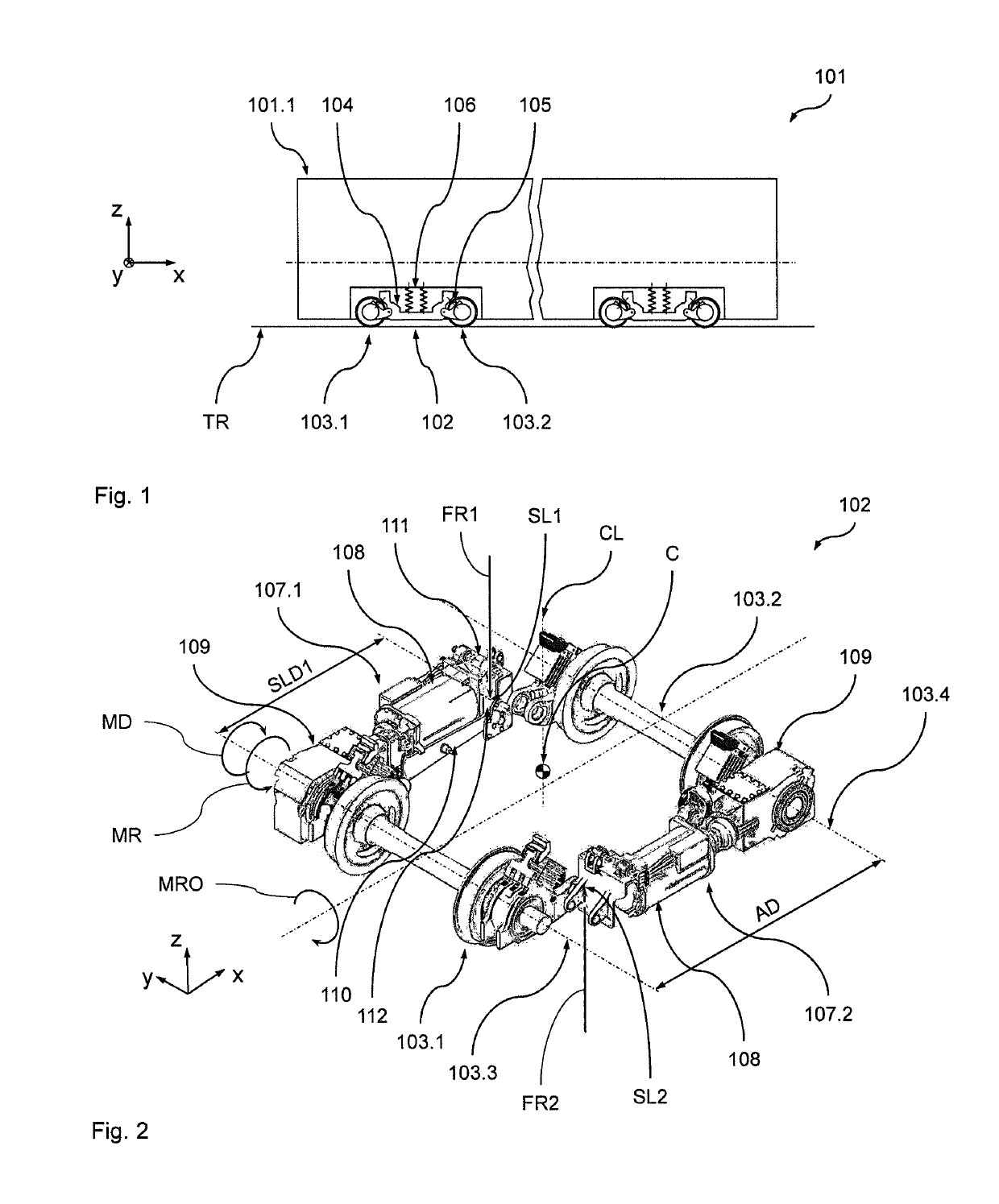
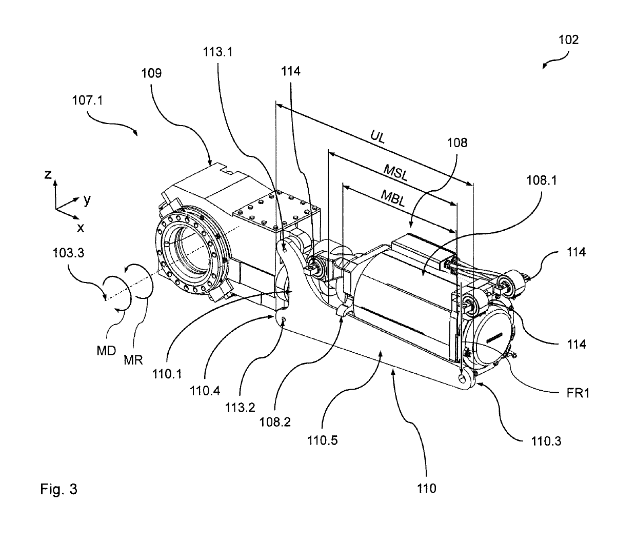
[0032]With reference to FIGS. 1 to 3 a preferred embodiment of a rail vehicle 101 according to the present invention comprising a preferred embodiment of a running gear 102 according to the invention will now be described in greater detail. In order to simplify the explanations given below, an xyz-coordinate system has been introduced into the Figures, wherein (on a straight, level track TR) the x-axis designates the longitudinal direction of the rail vehicle 101, the y-axis designates the transverse direction of the rail vehicle 101 and the z-axis designates the height direction of the rail vehicle 101 (the same, of course, applies for the running gear 102). It will be appreciated that all statements made in the following with respect to the position and orientation of components of the rail vehicle, unless otherwise stated, refer to a static situation with the rail vehicle 101 standing on a straight level track under nominal loading.

[0033]The vehicle 101 is a low floor rail vehicl...


PUM


Abstract

The present invention relates to a running gear of a rail vehicle defining a longitudinal direction, a transverse direction and a height direction, the running gear comprising a first wheel unit (103.1) and a second wheel unit (103.2) defining a wheel unit axle distance, a running gear frame (104) supported on the first wheel unit (103.1) and the second wheel unit (103.2), and a first drive unit (107.1) driving the first wheel unit (103.1). The first drive unit (107.1) comprises a first reaction moment support unit (110) connected to the running gear frame (104) at a first support location to balance a drive moment exerted onto the first wheel unit (103.1) by the first drive unit (107.1). The first support location, in the transverse direction, is laterally offset from a center of the running gear frame (104). The first support location, in the longitudinal direction, is located at a first support location distance from a first wheel unit axle of the first wheel unit (103.1), which is at least 35% of the wheel unit axle distance.

Description

BACKGROUND OF THE INVENTION[0001]The present invention relates to a running gear of a rail vehicle defining a longitudinal direction, a transverse direction and a height direction, the running gear comprising a first wheel unit and a second wheel unit defining a wheel unit axle distance, a running gear frame supported on the first wheel unit and the second wheel unit, and a first drive unit driving the first wheel unit. The first drive unit comprises a first reaction moment support unit connected to the running gear frame at a first support location to balance a drive moment exerted onto the first wheel unit by the first drive unit. The first support location, in the transverse direction, is laterally offset from a center of the running gear frame. The present invention further relates to a rail vehicle comprising such a running gear.[0002]In such running gears, the reaction moment necessary to be exerted on the drive unit to balance the positive moment (e.g. when accelerating) or n...

Claims


Application Information

Patent Timeline
Patent Type & Authority Patents(United States)
IPC IPC(8): B61F5/50B61F3/04
CPCB61F3/04B61F5/50B61C9/38B61D13/00
Inventor BIEKER, GUIDO
Owner BOMBARDIER TRANSPORTATION GMBH
Learn More