Hand-held power tool

a power tool and hand-held technology, applied in the field of hand-held power tools, can solve problems such as engine stall, and achieve the effect of excellent utilization of constructive spa

Active Publication Date: 2014-10-21
ANDREAS STIHL AG & CO KG
View PDF18 Cites 0 Cited by
  • Summary
  • Abstract
  • Description
  • Claims
  • Application Information

AI Technical Summary

Benefits of technology

[0003]It is an object of the present invention to provide a hand-held power tool of the aforementioned kind whose two-stroke engine has improved running behavior.
[0006]In order to avoid this, it is now proposed that, upon upward stroke of the piston, first the mixture inlet is connected with the crankcase before the air passage connects with the transfer passage. The connection or communication should take place only about a portion of the width of the mixture inlet. In this way it is ensured that the underpressure from the crankcase first is applied to the mixture passage and only subsequently is applied to the air passage. In this way, it is achieved that even for substantially closed throttle valve mixture can be sucked in through the crankcase. The deficiency in fuel supply into the combustion chamber that occurs upon fuel supply reversal from fuel being supplied through both passages to fuel being supplied through the mixture passage can therefore be prevented by construction-based measures. Since the mixture inlet is connected only about a portion of its width with the crankcase, this is of no consequence under full load where opening of the air passage before the mixture passage opens is desirable. By opening the mixture inlet only about a portion of its width before the air passage is connected to the transfer passage, the disadvantage of insufficient mixture supply upon acceleration, observed in engines with divided intake passage, can be prevented.
[0008]A simple constructive configuration results when the piston at its bottom edge has a cutout that connects the mixture inlet across the portion of its width with the crankcase. Advantageously, the width of the cutout, measured in circumferential direction of the piston, increases in a direction toward the crankcase. In this way, a gradual opening of the mixture inlet into the crankcase is achieved.
[0012]Advantageously, the piston has at least one piston recess for connecting the air passage and the transfer passage. In this connection, the piston recess connects advantageously the air passage with the transfer port. In this way, a complete scavenging of the transfer passage with scavenging air can be achieved. Advantageously, the two-stroke engine has at least one outlet-near and at least one outlet-remote transfer port wherein the outlet-near transfer port, upon upward stroke of the piston, is connected with the air passage before the outlet-remote transfer port connects with the air passage. In this way, filling of the transfer passages with scavenging air can be adjusted. This is in particular advantageous in case of transfer passages that extend underneath the outlet. With this transfer passage configuration, the outlet-near transfer passage sections are shorter than the outlet-remote transfer passage sections. Because the outlet-near transfer passage sections are connected. longer with the air passage, a uniform filling and, upon downward stroke of the piston, a uniform scavenging action of the combustion chamber can be achieved. The outlet-near transfer port is advantageously connected with the air passage after the mixture inlet has been connected across its entire width with the crankcase.
[0013]The two-stroke engine is advantageously arranged horizontally in the housing of the power tool so that the piston in the cylinder is moving approximately horizontally wherein the carburetor in the rest position of the power tool is arranged above the cylinder. In this way, there is an excellent utilization of the constructive space that is available. The mixture passage is arranged in the carburetor in particular above the air passage. This provides for an advantageous extension / configuration of the passages. The arrangement of the mixture passage above the air passage favors however as a result of the force of gravity a transfer of fuel into the air passage. In this way, the proposed opening of the mixture inlet across a portion of its width toward the crankcase before opening of the air passage is expedient in particular for two-stroke engines in which the mixture passage is arranged above the air passage. The power tool is in particular a motor chainsaw with a top handle. The horizontal arrangement of the motor and the arrangement of the carburetor above the cylinder and crankcase are particularly advantageous in such power tools.

Problems solved by technology

It has been found that this short period of time in which only little fuel reaches the combustion chamber may be sufficient to cause the engine to stall.

Method used


Image

  • Hand-held power tool
  • Hand-held power tool
  • Hand-held power tool

Examples


Embodiment Construction

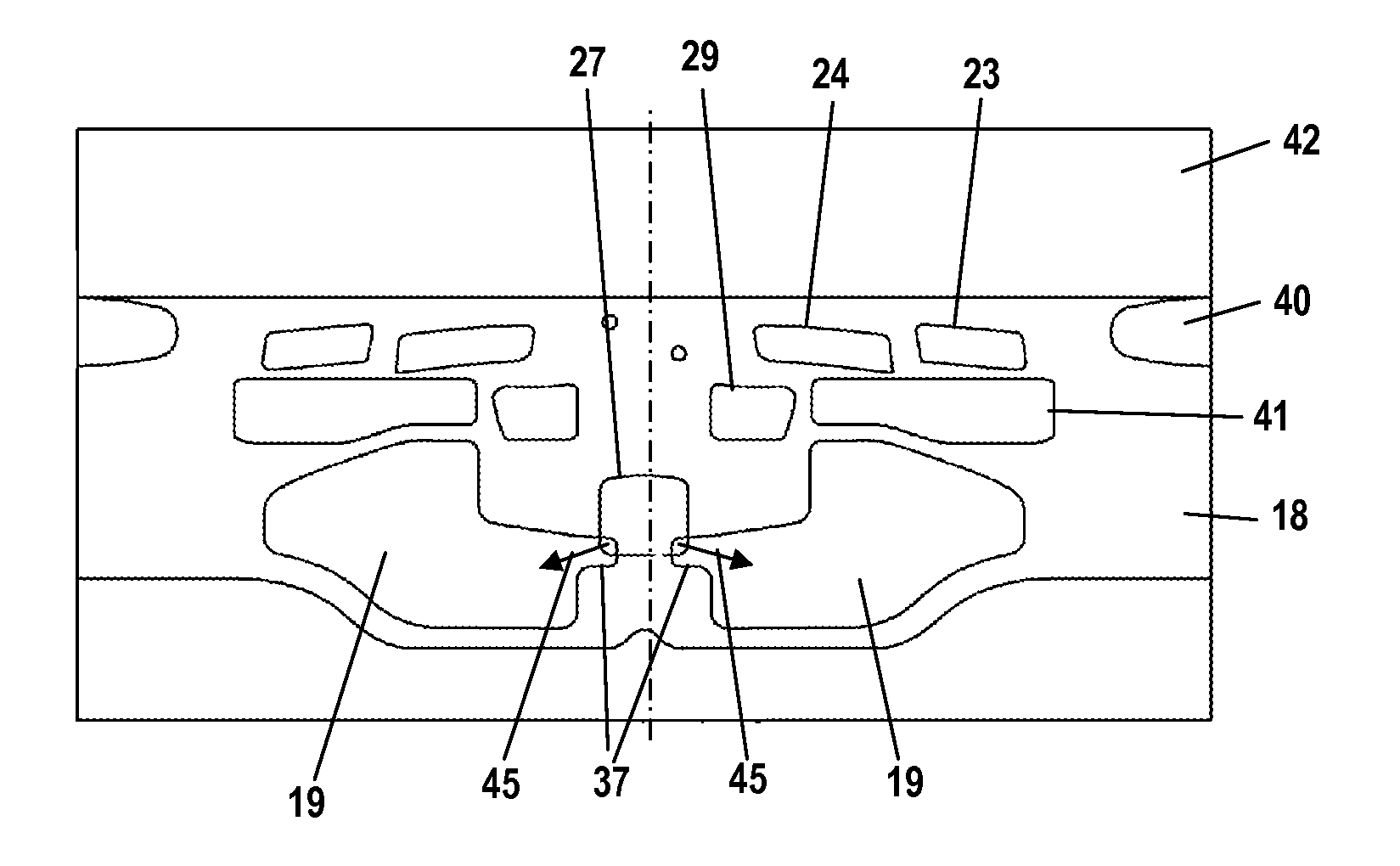
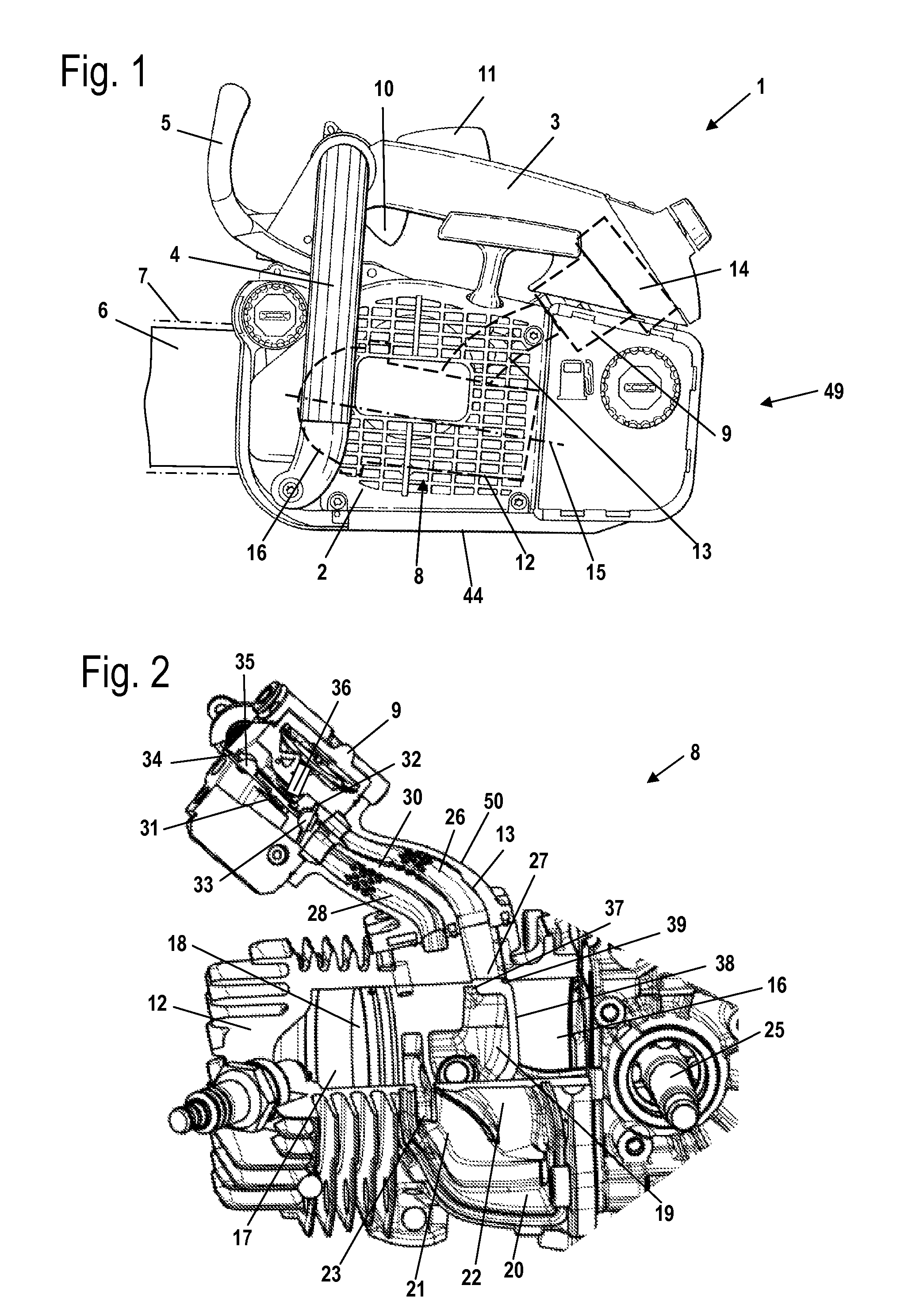
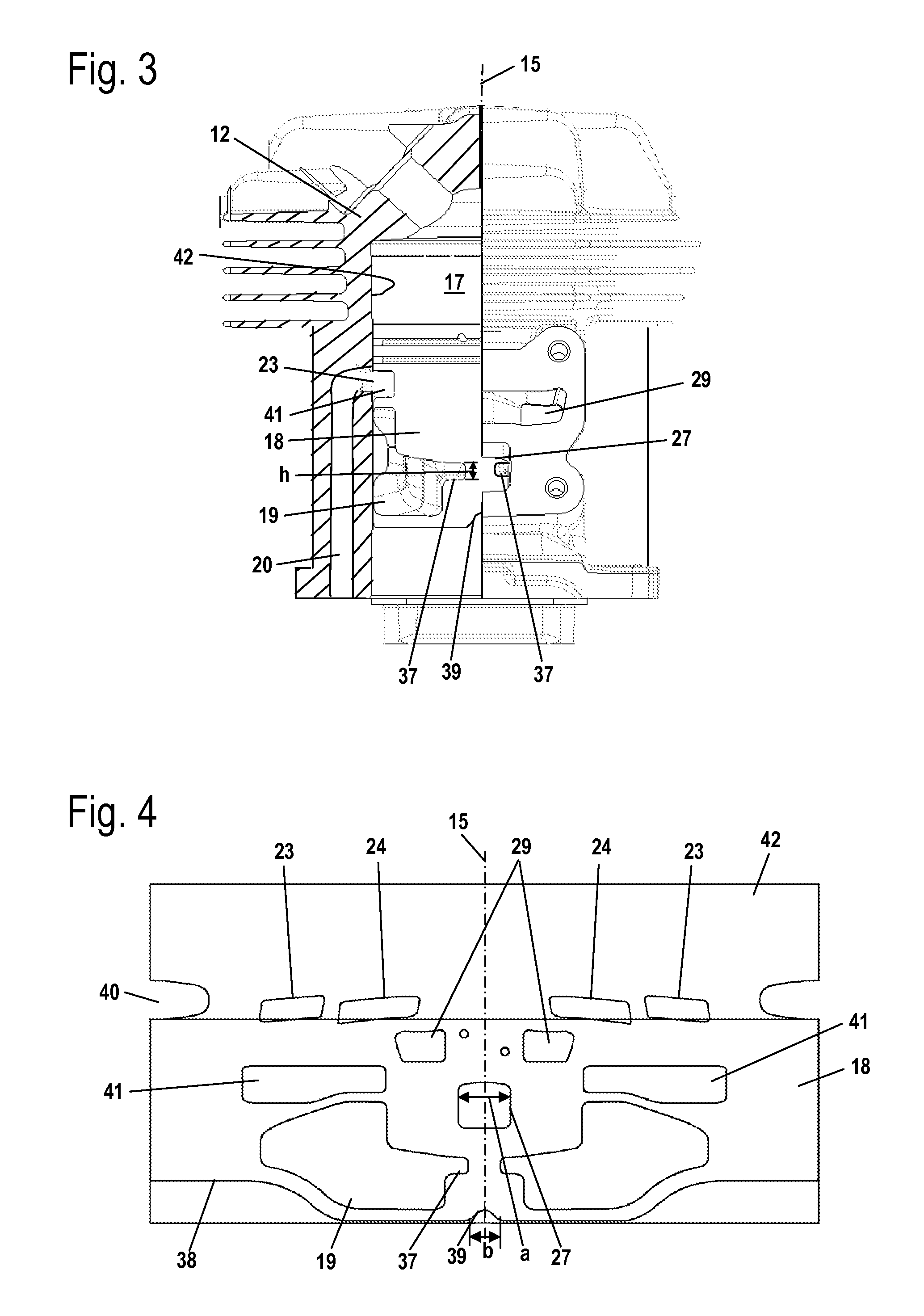
[0023]FIG. 1 shows as an embodiment of a hand-held power tool a motor chainsaw 1. However, the two-stroke engine described in the following can also be used in other hand-held power tools such as cut-off machines, trimmers or the like. The motor chainsaw 1 has a housing 2 on which a top handle 3 as well as a lateral grip pipe 4 are secured. At the front end of the housing 2 a guidebar 6 is attached and projects forwardly. A saw chain 7, schematically indicated in FIG. 1, is arranged on the guidebar so as to circulate about it. At the front end of the grip pipe 4 a hand guard 5 is arranged that serves simultaneously as a chain brake. At the top handle 3 there is a throttle lever 10 and a throttle lever lock 11. In the housing 2 a two-stroke engine 8 is disposed. As shown in FIG. 1, the two-stroke engine 8 is positioned horizontally within the housing 2. The two-stroke engine 8 has a cylinder 12 with a longitudinal cylinder axis 15. The longitudinal cylinder axis 15 is positioned at a...


PUM

PropertyMeasurementUnit
crank angleaaaaaaaaaa

Abstract

A hand-held power tool has a two-stroke engine with a cylinder with combustion chamber and a piston disposed therein that drives a crankshaft supported in a crankcase. In at least one piston position, crankcase and combustion chamber are connected by a transfer passage. An air passage supplies in at least one piston position combustion air to the transfer passage. A mixture passage for fuel / air mixture is provided. Air and mixture passages in operation are at least partially connected to each other. Part of the mixture passage is formed in a carburetor where a fuel port opens into the mixture passage. The mixture passage opens into the crankcase with a piston-controlled mixture inlet having a width in circumferential direction of the cylinder. Upon upward piston stroke the mixture inlet is connected to the crankcase with a portion of the width before a connection of air passage and transfer passage is established.

Description

BACKGROUND OF THE INVENTION[0001]The invention relates to a hand-held power tool comprising a two-stroke engine wherein the two-stroke engine has a cylinder in which a combustion chamber is formed that is delimited by a piston. The piston drives in rotation a crankshaft that is rotatably supported in a crankcase. The crankcase in at least one position of the piston is connected by means of at least one transfer passage to the combustion chamber. An air passage for supply of combustion air is provided. A mixture passage for supply of fuel / air mixture is also provided. The air passage and the mixture passage are at least partially connected to each other in operation. A section of the mixture passage is formed in a carburetor. In the carburetor at least one fuel port opens into the mixture passage. The air passage in at least one position of the piston supplies combustion air into the at least one transfer passage. The mixture passage opens with a piston-controlled mixture inlet into ...

Claims


Application Information

Patent Timeline
Patent Type & Authority Patents(United States)
IPC IPC(8): F02B63/02F02B33/04F02B25/22F02B75/02F02B25/00F02B25/14
CPCF02B63/02F02B25/22F02B33/04F02B2075/025F02B25/14
Inventor KUNERT, NIELSGRETHER, MICHAEL
Owner ANDREAS STIHL AG & CO KG
Why Eureka
Try Eureka