Obstacle avoidance device

a technology of obstacle avoidance and obstacle, which is applied in the direction of process control, television system, instruments, etc., can solve the problems of inability to achieve obstacle avoidance, poor flight experience, and difficulty in distinguishing very small obstacles, so as to improve the stability of obstacle avoidance modules, and collect images

Active Publication Date: 2019-04-16
HAOXIANG ELECTRIC ENERGY KUNSHAN
View PDF11 Cites 1 Cited by
  • Summary
  • Abstract
  • Description
  • Claims
  • Application Information

AI Technical Summary

Benefits of technology

[0008]A technical problem of the present invention to be solved is to provide an obstacle avoidance device, which is able to keep a stable attitude while an unmanned mobile device is unstable and changes an attitude thereof, so as to effectively avoid obstacles.
[0011]an obstacle avoidance module fixed with the stabilization platform, so as to reduce interferences to detecting the surroundings by the obstacle avoidance module when the unmanned mobile device acts.
[0025]The obstacle avoidance module is installed on the stabilization platform to enhance the stability of the obstacle avoidance module; and no matter how the unmanned mobile device acts, it is maintained that the obstacle avoidance module stably faces towards one direction, so that images collected by the obstacle avoidance module are more stable. Therefore, an optical lens with a higher resolution is used to clearly distinguish smaller obstacles, thus more effectively avoiding obstacles and constraining an action of the unmanned mobile device no longer.
[0026]The platform camera and the obstacle avoidance module are simultaneously installed on the stabilization holder, such that the stabilization platform becomes a shared structure, so as to save the installation space and cost. Furthermore, the platform camera is rotatably installed to the gap of the frame structure of the stabilization holder, which means that a shaft is added to the stabilization platform; while rotating within the gap, the platform camera will not be blocked by the stabilization holder during the shooting process at any angles, which makes the shooting angle less restricted.

Problems solved by technology

Firstly, the aircraft body of the UAV has big vibrations, which causes that the optical image information collected by the sensor also correspondingly shakes at high frequency, so that the obstacle avoidance lens with high resolution is unable to be applied, thus it is difficult to distinguish very small obstacles, such as wires.
Secondly, the attitude will change during the flight, so that the lens of the obstacle avoidance module is unable to always aim at the plane of the flight direction, thereby the obstacle avoidance is unable to be achieved.
The traditional method to solve the above problems is to limit the attitude change angle of the UAV in the course of movement, that is, to limit the flight speed of the UAV, resulting in poor flight experience, and also unable to achieve the obstacle avoidance in the case of body vibration.

Method used


Image

  • Obstacle avoidance device
  • Obstacle avoidance device
  • Obstacle avoidance device

Examples


Embodiment Construction

[0034]To more obviously understand the foregoing objects, features and advantages of the present invention, the specific embodiments of the present invention will be described in detail with reference to the accompanying drawings as follows.

[0035]Many specific details are set forth in the following description to facilitate a thorough understanding of the present invention. The present invention is able to be embodied in many other ways different from those described herein, those skilled in the art will be able to make similar generalizations without departing from the spirit of the present invention. Therefore, the present invention is not limited to the specific embodiments disclosed below.

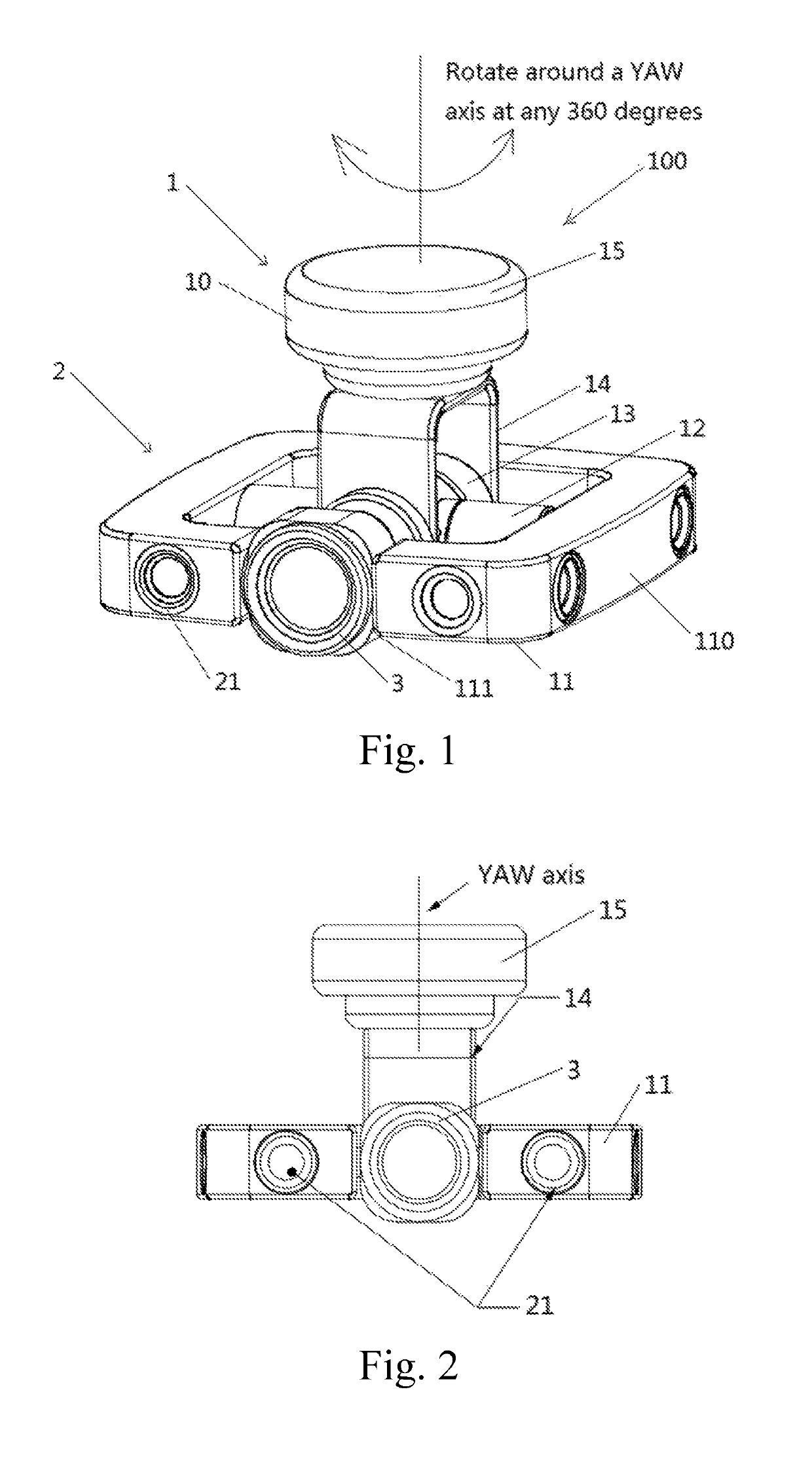
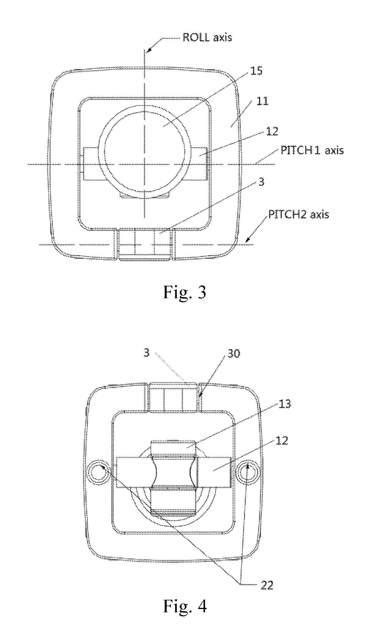
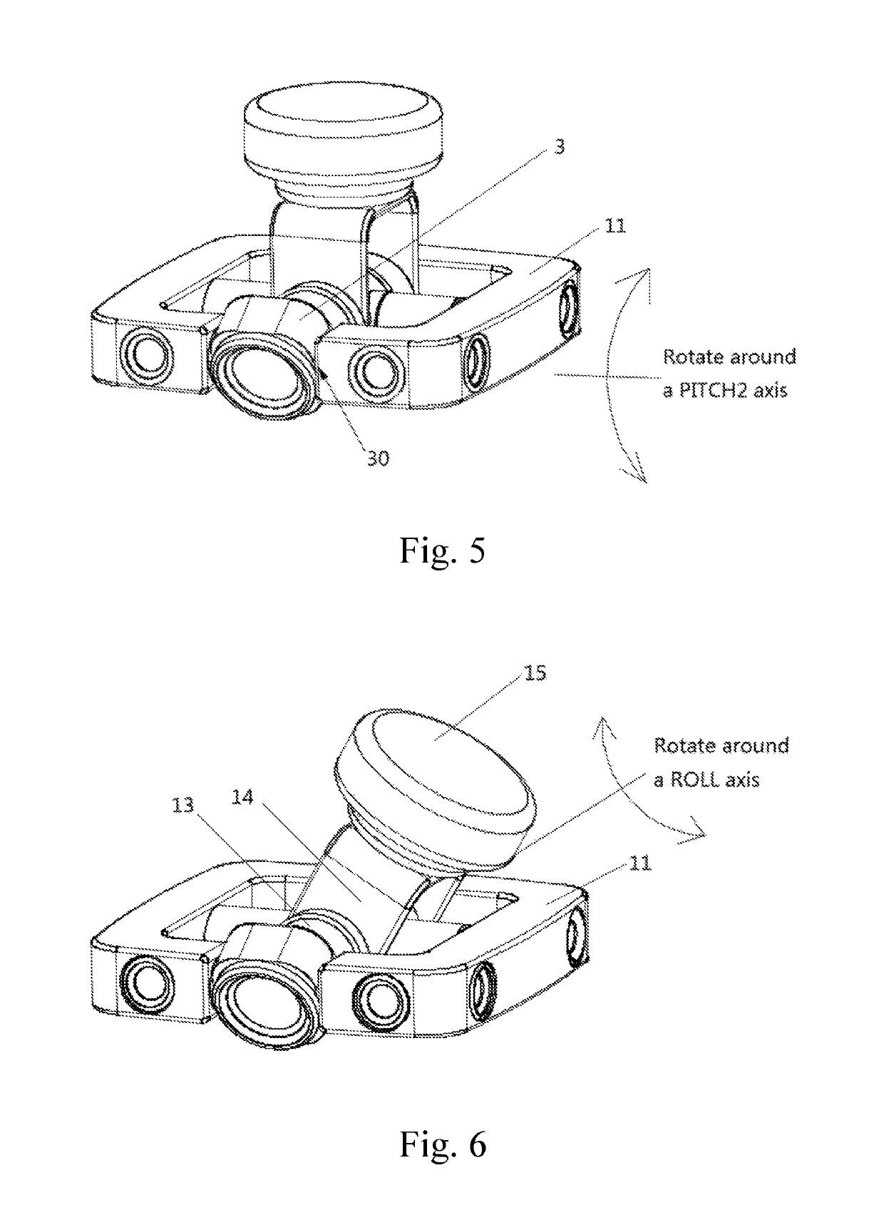
[0036]Referring to FIGS. 1-6, an obstacle avoidance device 100 according to a preferred embodiment of the present invention is illustrated, which comprises a stabilization platform 1 and an obstacle avoidance module 2 and is adapted for detecting surroundings of an unmanned mobile device. The s...


PUM


Abstract

An obstacle avoidance device for detecting surroundings of an unmanned mobile device is disclosed, which includes a stabilization platform connected with the unmanned mobile device, wherein the stabilization platform includes a stabilizer for ensuring stably bearing at least one platform camera; and an obstacle avoidance module fixed with the stabilization platform, so as to reduce interferences to detecting the surroundings by the obstacle avoidance module when the unmanned mobile device acts. The obstacle avoidance device of the present invention is able to keep a stable attitude while the unmanned mobile device is unstable and changes an attitude thereof, so as to effectively avoid obstacles.

Description

CROSS REFERENCE OF RELATED APPLICATION[0001]The present invention claims priority under 35 U.S.C. 119(a-d) to CN 201611223341.0, filed Dec. 26, 2016; and CN 200621440413.2, filed Dec. 26, 2016.BACKGROUND OF THE PRESENT INVENTION[0002]Field of Invention[0003]The present invention relates to an obstacle avoidance technology, and more particularly to an obstacle avoidance device.[0004]Description of Related Arts[0005]The UAV (unmanned aerial vehicle) vision navigation system has technical characteristics of real-time modeling, autonomous positioning and navigation in a complex unknown flight environment. Through being equipped with the visible light camera, the infrared camera, the laser rangefinder and other sensors, the UAV platform can simultaneously collect multidimensional flight environment information; interact data with ground station and collaboratively compute framework through an airborne processor, to real-time reconstruct a three-dimensional model of an unknown flight envi...

Claims


Application Information

Patent Timeline
Patent Type & Authority Patents(United States)
IPC IPC(8): B64D47/08G05D1/00F16M11/10B64C39/02G03B17/56G03B15/00H04N5/232
CPCB64D47/08B64C39/024F16M11/10G03B15/006G05D1/0038G05D1/0094H04N5/2328G03B17/561F16M2200/04B64C2201/127F16M11/18F16M11/205F16M13/02F16M2200/044H04N23/685B64U2101/30B64U20/87
Inventor TIAN, YUJIANG, WENYAN
Owner HAOXIANG ELECTRIC ENERGY KUNSHAN
Why Eureka
Try Eureka