Sheet-speed reduction mechanism for fan wheel

a fan wheel and speed reduction technology, which is applied in the direction of thin material processing, article separation, article delivery, etc., can solve the problems of non-uniform intervals for transport, unstable attitude of the signature in the fan wheel, damage or deformation of the front end of the signature, etc., to reduce the speed of an advancing sheet, suppress the bouncing off of the sheet, and stable attitude

Inactive Publication Date: 2008-10-16
KOMORI CORP
View PDF3 Cites 2 Cited by
  • Summary
  • Abstract
  • Description
  • Claims
  • Application Information

AI Technical Summary

Benefits of technology

[0009]In this respect, the present invention has been made for the purpose of solving the above-described problems. An object of the present invention is to provide a sheet-speed reduction mechanism for a fan wheel, which mechanism reduces the speed of an advancing sheet so as to prevent the sheet from being damaged or deformed, and also to suppress the bouncing off of the sheet so that the sheet can be discharged with a stable attitude.

Problems solved by technology

However, in such conventional fan wheel, a signature slid between the fan blades is caused to hit the stopper at the same speed as the sliding speed of the signature into the fan wheel.
For this reason, the front end of the signature may be damaged or deformed.
In addition, the signature may be caused to bounce off when hitting the stopper, thus protruding from the fan wheel.
As a result, the attitude of the signature in the fan wheel becomes unstable.
If the signature is discharged onto the delivery conveyor in this unstable state, the following problem may occur.
Specifically, a signature may be caused to overlap the preceding one, so that the intervals for the transport may become non-uniform.
In addition, if a signature is bent or displaced, the accuracy in the delivery may be adversely affected.

Method used


Image

  • Sheet-speed reduction mechanism for fan wheel
  • Sheet-speed reduction mechanism for fan wheel
  • Sheet-speed reduction mechanism for fan wheel

Examples


Embodiment Construction

[0034]Hereinafter, a sheet-speed reduction mechanism for a fan wheel according to the present invention will be described in detail with reference to the accompanying drawings.

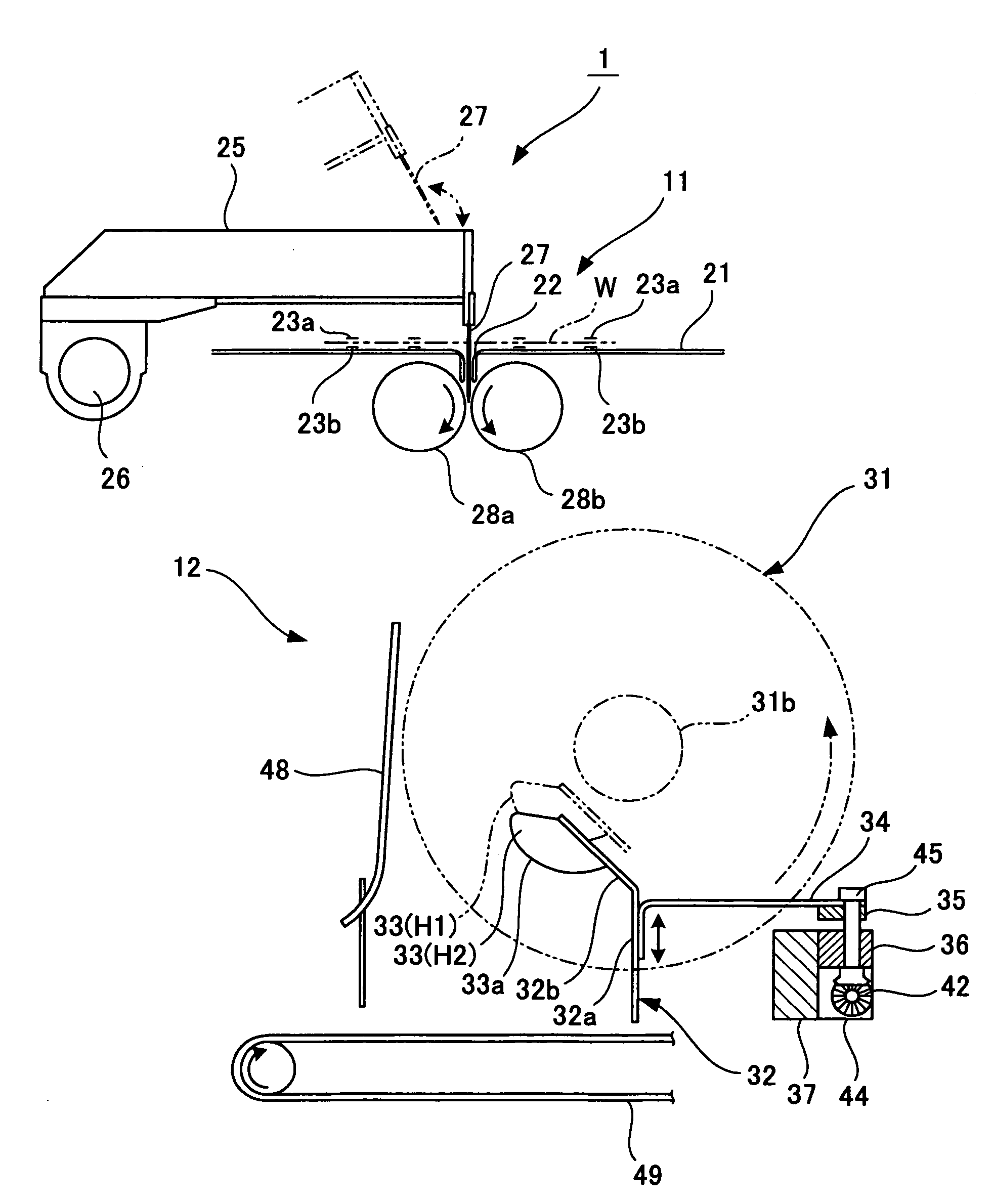
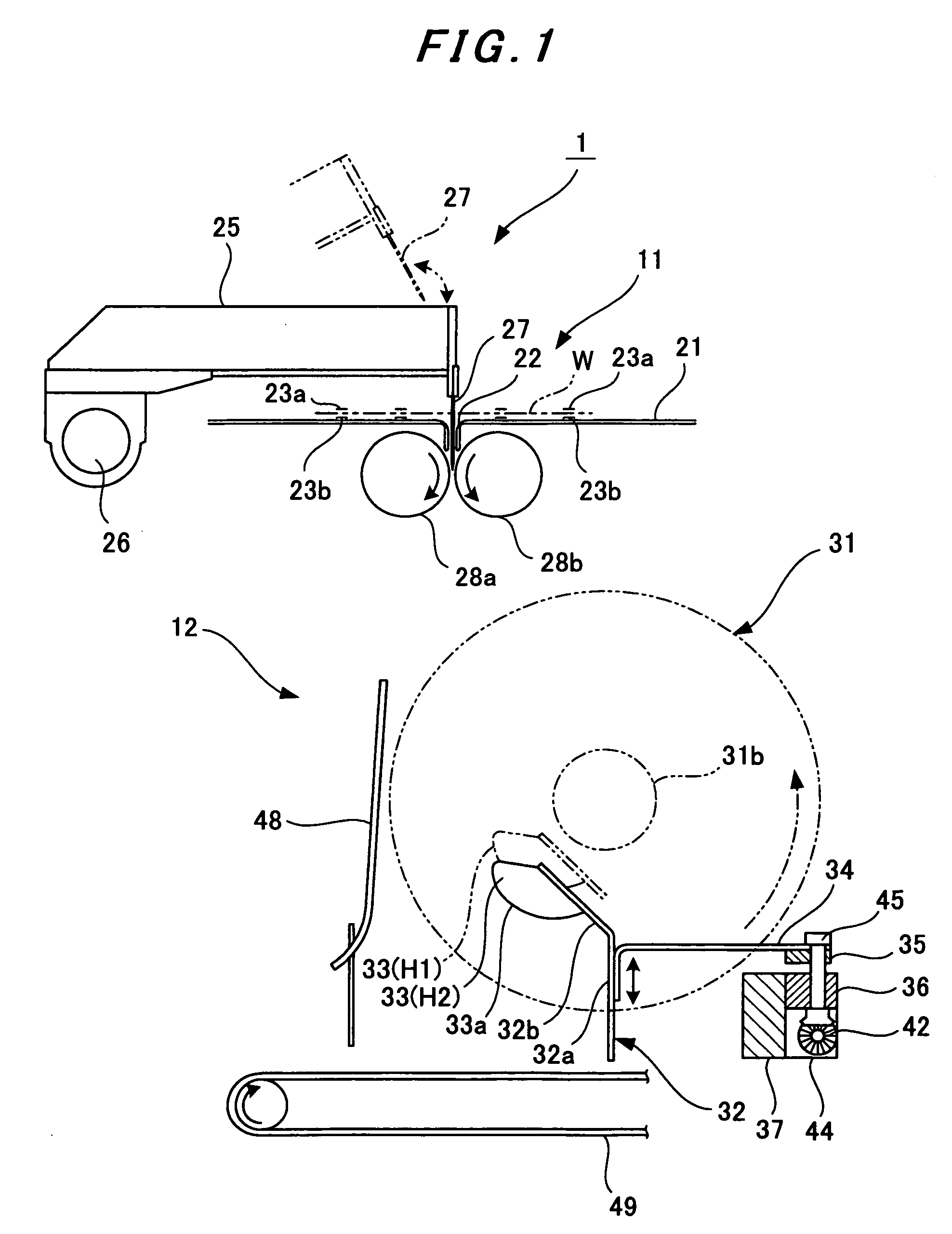
[0035]As shown in FIG. 1, a folder 1 is installed in an unillustrated web-fed rotary printing press. The folder 1 is provided with a chopper folding device 11 for chopper-folding a signature W. In addition, a delivery device 12 for delivering the signature W to the outside of the printing press is provided to the downstream (the lower side), in the signature transporting direction, of the chopper folding device 11.

[0036]As shown in FIG. 1, a plate-shaped table 21 is substantially horizontally disposed in the chopper folding device 11. Above the top surface of the table 21, multiple transporting belts, that is, a pair of upper and lower belts 23a and 23b are provided in a stretched manner. The signature W is held by these transporting belts 23a and 23b from above and below so as to be transported. In addition, ...


PUM

PropertyMeasurementUnit
speedaaaaaaaaaa
radius of curvatureaaaaaaaaaa
thicknessaaaaaaaaaa

Abstract

A sheet-speed reduction mechanism for a fan wheel including: fan wheels that hold, between fan blades thereof, a signature transported from a printing press thereto, and that rotates with the held signature; a stopper portion that restricts the front end of the signature held between the fan blades, and that then discharges the signature from the inside of the fan wheels; and speed-reduction guides that presses a surface of the signature advancing between the fan blades before the front end of the signature comes into contact with the stopper portion, so as to reduce the advancing speed of the signature.

Description

BACKGROUND OF THE INVENTION[0001]1. Field of the Invention[0002]The present invention relates to a sheet-speed reduction mechanism for a fan wheel by which mechanism the speed of a signature transported from a folder of a printing press is reduced before the signature is held in the fan wheel.[0003]2. Description of the Related Art[0004]A web-fed rotary printing press is provided with a folder for forming a signature (sheet) from a web. The web is dried and cooled after a print is made thereon, and thereafter the folder cuts the web into pieces each having a predetermined length. The folder then folds each piece of the web along the width direction, or along the longitudinal direction, of the piece, so that the signature is formed. The signature thus folded by the folder is delivered to the outside of the printing press by a delivery device which is provided at the most downstream side, in a direction in which the signatures (web) are transported (hereinafter, referred to simply as ...

Claims


Application Information

Patent Timeline
Patent Type & Authority Applications(United States)
IPC IPC(8): B65H3/48
CPCB65H29/40B65H29/68B65H2301/44921B65H2403/52B65H2404/654B65H2404/656B65H2511/22B65H2513/11B65H2601/2531B65H2701/1932B65H2220/02B65H2220/11B65H2220/01B65H29/52B65H2301/17B65H2511/13
Inventor INOUE, HIROSHI
Owner KOMORI CORP
Why Eureka
Try Eureka