Article Transfer Facility

a technology for transferring facilities and articles, which is applied in the direction of de-stacking articles, packaging, and program-controlled manipulators, etc. it can solve the problems of limiting the gap between articles being likely to be formed, so as to reduce the possibility of articles falling or collapsing, improve the efficiency of storing articles, and stabilize the attitude of articles loaded

Pending Publication Date: 2022-01-13
DAIFUKU CO LTD
View PDF4 Cites 1 Cited by
  • Summary
  • Abstract
  • Description
  • Claims
  • Application Information

AI Technical Summary

Benefits of technology

[0007]Therefore, there is a demand for realization of an article transfer facility that can make it easier to ensure the stability of the attitude of the articles on the second support member, and improve efficiency in storing the articles when transferring articles from the first support member to the second support member.
[0014]With this characteristic configuration, the second support member supported by the support mechanism at the predetermined position is in an inclined orientation such that a target corner portion that is one of a plurality of corner portions of the mounting surface of the second support member is located lower than the other corner portions. Therefore, the bottom surface of the article stored in the second support member is supported by the mounting surface of the second support member or the upper surface of another article located below adjacent thereto, and also the side surface of the article on the target corner side is supported by the side wall portion of the second support member of the side surface of another article that is located laterally adjacent thereto. As a result, it is possible to stabilize the attitude of the articles loaded onto the second support member, and reduce the possibility of the articles falling or collapsing. Also, depending on the inclination angle and the degree of smoothness of the mounting surface, it is possible to transfer the articles loaded onto the second support member to the target corner portion side along the inclination of the mounting surface, and narrower a gap between articles that are adjacent to each other, or a gap between articles and the side wall portion. If this is the case, it is also possible to improve efficiency in storing articles on the second support member. As described above, with this configuration, it is possible to make it easier to ensure the stability of the attitude of articles on the second support member and improve efficiency in storing the articles.

Problems solved by technology

In such an article transfer facility, for example, in a case where the loaded articles are in an unstable attitude such as a case where a plurality of articles are loaded onto the second support member in a stacked state, there is the possibility of the articles falling or collapsing.
Also, articles are loaded on the second support member by the transfer device so that the articles do not interfere with each other, and therefore gaps are likely to be formed between the articles, and there is a limit in improving efficiency in storing the articles.

Method used


Image

  • Article Transfer Facility
  • Article Transfer Facility
  • Article Transfer Facility

Examples


Embodiment Construction

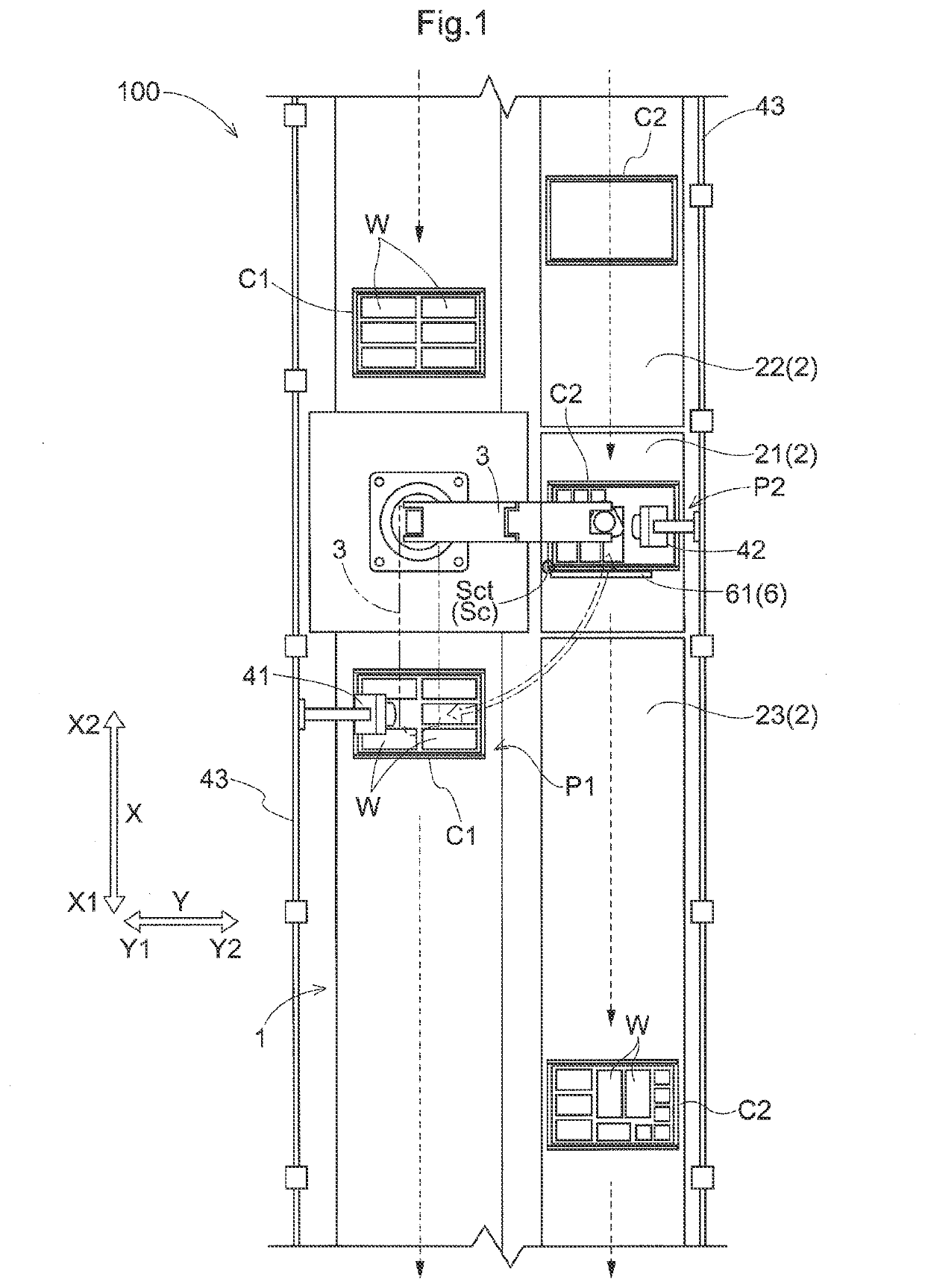
[0027]The following describes an article transfer facility 100 according to an embodiment with reference to the drawings. As shown in FIG. 1, the article transfer facility 100 performs transfer work to transfer articles W from a first container C1 to a second container C2. The first container C1 and the second container C2 correspond to a “first support member” and a “second support member” each of which supports articles W, respectively.

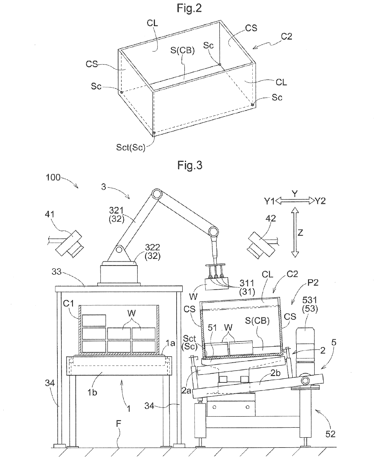
[0028]As shown in FIG. 2, each of the second containers C2 has a bottom portion CB with a mounting surface S onto which articles W are to be placed, a pair of long-wall portions CL that respectively stand on a pair of long sides of the mounting surface S, and a pair of short-wall portions CS that respectively stand on a pair of short sides of the mounting surface S. As described above, each of the second containers C2 has a rectangular mounting surface S onto which articles W are to be mounted, and is formed in a box-shape with an open upper surface...


PUM


Abstract

An article transfer facility (100) includes a transfer device (3) that performs a first operation to take out an article (W) that are supported by a first container (C1), from the first container (C1), and a second operation to load the article (W) taken out from the first container (C1), onto a second container (C2); and an inclination device (5) that supports the second container (C2) at a predetermined position (P2), wherein the second container (C2) has a rectangular mounting surface (S) onto which the articles (W) are to be mounted, and is formed in a box shape with an open upper surface, and the inclination device (5) supports the second container (C2) in an inclined state such that a target corner portion (Sct) that is one of a plurality of corner portions (Sc) of the mounting surface (S) is located lower than the other corner portions (Sc).

Description

CROSS-REFERENCE TO RELATED APPLICATIONS[0001]This application is the United States national phase of International Application No. PCT / JP2019 / 044371 filed Nov. 12, 2019, and claims priority to Japanese Patent Application No. 2018-213660 filed Nov. 14, 2018, the disclosures of which are hereby incorporated by reference in their entirety.BACKGROUND OF THE INVENTION1. Field of the Invention[0002]The present invention relates to an article transfer facility that transfers articles.2. Description of Related Art[0003]An example of such an article transfer facility is disclosed in Patent Document 1 shown below. In the following description of background art, the names of the members and the reference numerals used in Patent Document 1 are quoted in parentheses.[0004]Patent Document 1 discloses an article transfer article that is provided with a transfer device (transfer device 3) that transfers an article (article W) from a first support member (first container C1) and a second support mem...

Claims


Application Information

Patent Timeline
Patent Type & Authority Applications(United States)
IPC IPC(8): B25J9/16B25J13/08B65G47/90B65G57/04B65B5/08B65B17/00
CPCB25J9/16B25J13/08B65B17/00B65G57/04B65B5/08B65G47/90B65G61/00B65G2203/041B65G2201/0258B65G2203/0233B65G47/917B65B5/105B65G47/91B65G60/00B25J9/0093B65G2201/02
Inventor MORIKUBO, MITSUOTAI, YOSHIKAZUIWAI, MASAMIGONDOH, TAKUYAMINOO, ATSUSHIOHGITA, KAZUYOSHIONAYAMA, MANABUMORI, KIYOJI
Owner DAIFUKU CO LTD
Why Eureka
Try Eureka