Venting device for fuel tank

a technology for venting devices and fuel tanks, which is applied in the direction of liquid fuel feeders, machines/engines, combustion air/fuel air treatment, etc., can solve the problems that the valve cannot respond adequately to prevent fuel, and achieve the effects of enhancing sealing the valve body, limiting the rise in the internal pressure of the tank, and easy formation

Active Publication Date: 2010-10-12
TOYODA GOSEI CO LTD
View PDF13 Cites 2 Cited by
  • Summary
  • Abstract
  • Description
  • Claims
  • Application Information

AI Technical Summary

Benefits of technology

[0007]An advantage of some aspects of the invention is to provide a fuel tank venting device affording in a simple design a pressure valve that is able to effectively prevent fuel spray-back even if tank internal pressure should rise suddenly during fueling.
[0009]According to this first mode, during fueling, when the fuel level in the fuel tank exceeds a first level, tank internal pressure will rise due to closing of the first fuel cutoff valve. Through the second fuel cutoff valve, the elevated tank internal pressure will come to bear on the valve body of the pressure valve of the fuel tank valve unit, whereupon the valve body will open up the valve aperture in opposition to the spring force of the spring. The tank internal pressure will thereby escape to the canister through the pressure valve of the fuel tank valve unit, thus preventing spray-back from the inlet pipe. At times other than fueling, the pressure valve will prevent fuel from spilling out from the second fuel cutoff valve; and by opening when tank internal pressure rises will limit the rise in tank internal pressure. The valve part of the valve body is perforated by an orifice. In the event of a sudden rise in tank internal pressure, the orifice will allow slight escape of tank internal pressure prior to opening of the pressure valve, thus acting to limit a sudden rise in tank internal pressure and to prevent spray-back by the pressure valve during fueling; and at times other than fueling will provide enhanced action to prevent fuel from seeping into the canister in the event of a sudden rise in tank internal pressure. Such an orifice may be easily formed so as to pass through the valve part, with no need to modify the design for enhancing sealing of the valve body or to modify the shape of the components which define the valve chamber, or the like.
[0010]Moreover, because the pressure valve is defined by a cup-shaped valve body, it is able to close in a more stable attitude as compared with a ball valve arrangement. Additionally, because the spring is housed in a spring chamber, i.e. it is bounded by the valve body, it will not cause disturbance of the flow through the valve chamber. Accordingly, tank internal pressure will be able to escape rapidly when the pressure valve is open.
[0011]In a second mode of the present invention, the casing has a first valve chamber-defining part of tubular shape projecting from the outside wall of the first connector tube part, and a second valve chamber-defining part formed in the end part of the second connector tube part and unified with the first valve chamber-defining part to define the valve chamber; and the second valve chamber-defining part has a guide wall projecting towards the valve chamber and adapted to guide the side wall of the valve body, wherein the guide wall defines in relation to the inside wall of the first valve chamber-defining part a valve chamber internal passage situated therebetween. This guide wall affords sliding of the valve body in a stable attitude; and because the guide wall defines between itself and the inside wall of the first valve chamber-defining part a valve chamber internal passage which is situated therebetween, flow resistance of the valve body when open can be reduced, allowing tank internal pressure to escape rapidly.
[0012]In a third mode of the present invention, the guide wall is notched in a portion thereof to constitute a notched passage of progressively larger passage area going from the valve chamber towards the first flow passage. With this design, the guide wall is able to guide the valve body, while the provision of the notched passage, which boosts flow into the valve chamber internal passage, serves to further reduce flow resistance.

Problems solved by technology

However, a problem with the check valve of the conventional fuel tank venting device is that if there is a sudden rise in tank internal pressure, the valve may not be able to respond adequately to prevent fuel from seeping into the canister or to prevent fuel from being sprayed back during fueling.

Method used


Image

  • Venting device for fuel tank
  • Venting device for fuel tank
  • Venting device for fuel tank

Examples


Embodiment Construction

[0020](1) General Configuration of Fuel Tank Venting Device FS

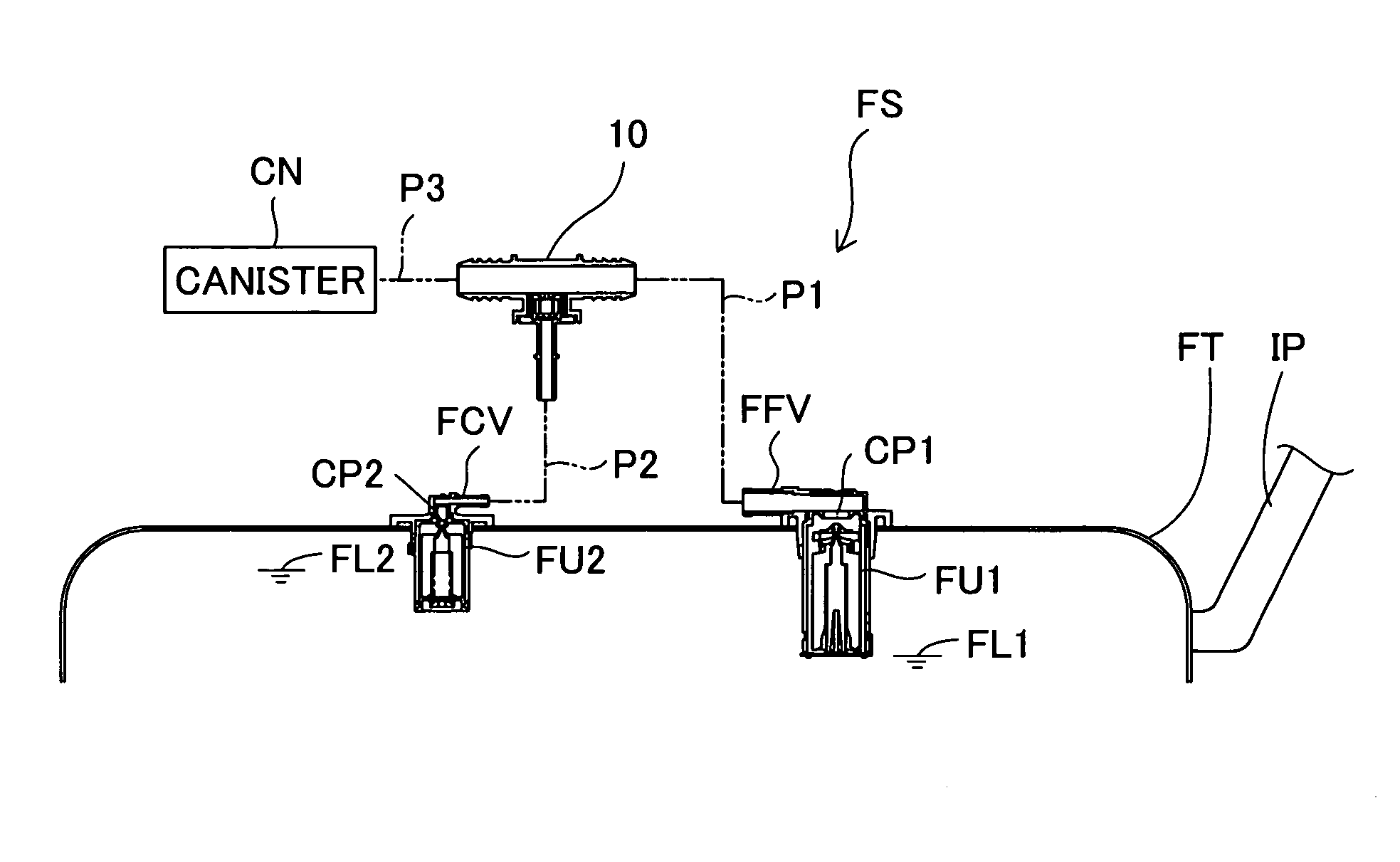
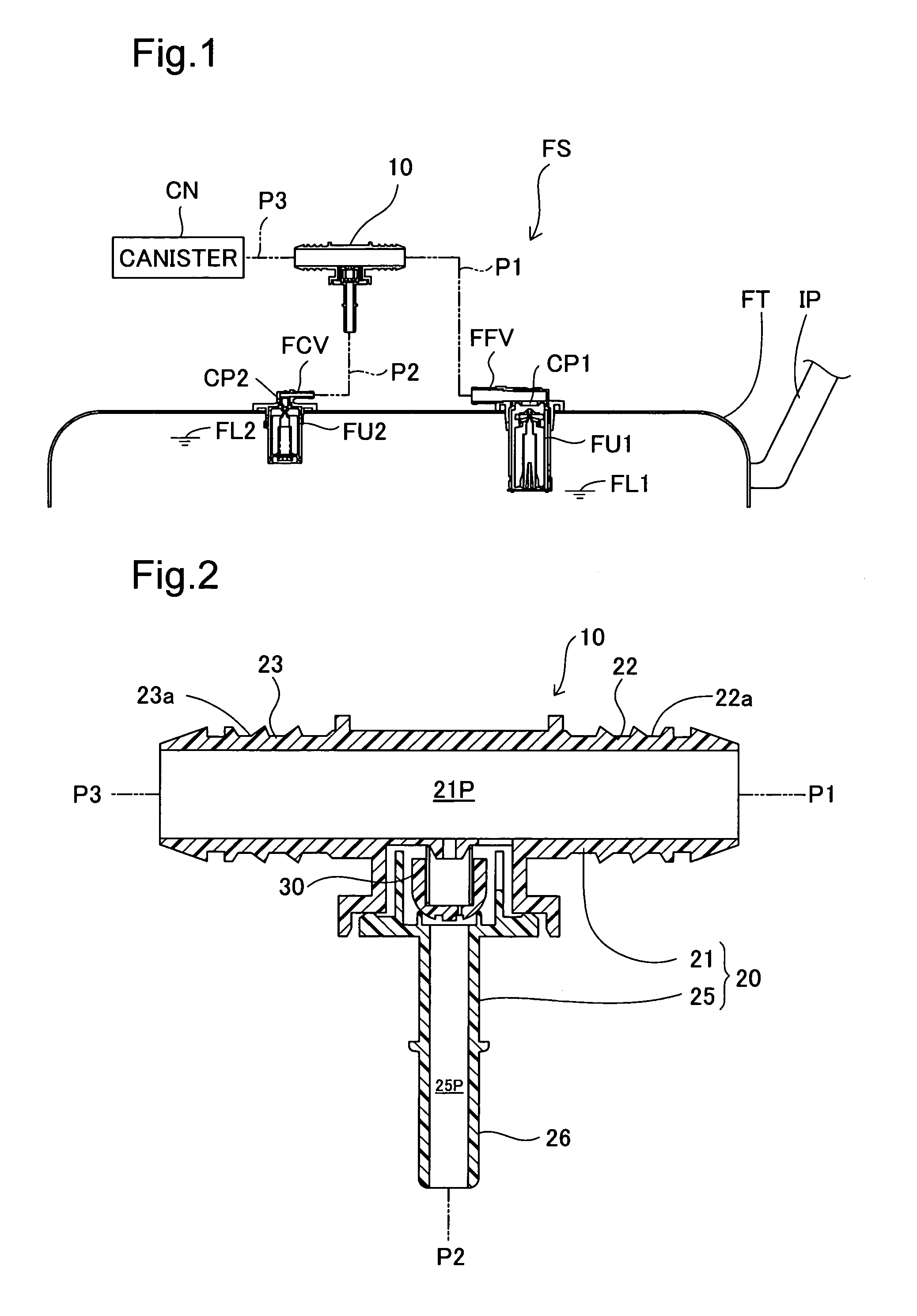
[0021]FIG. 1 shows a fuel tank venting device equipped with a fuel tank valve unit in accordance with an embodiment of the present invention. The fuel tank venting device FS is furnished with a full fuel control valve FFV (first cutoff valve) and a rollover valve FCV (second cutoff valve)of so-called ‘outside-tank’ design mounted on the upper wall inside a flattened fuel tank FT; a fuel tank valve unit 10 positioned to the outside of the fuel tank FT; a canister CN; and connector pipes connecting these. The full fuel control valve FFV is a valve designed so that a first float mechanism FU1 will uplift and close a first connecting passage CP1 when the fuel level inside the fuel tank FT has reached a first level FL1 during fueling. The rollover valve FCV is a valve that is situated so as to ensure venting to the outside even if the vehicle should tilt, and that is designed so that a second float mechanism FU2 will uplift an...


PUM


Abstract

The fuel tank venting device is furnished with a full fuel control valve and a rollover valve that are installed on a fuel tank, and a fuel tank valve unit having a pressure valve that is situated between a canister and the two valves. The pressure valve is furnished with a casing that has a valve chamber, a valve body housed within the valve chamber, and a spring. The valve body has a disk-shaped valve part and a side wall that projects with tubular contours from the outside perimeter of the valve part, and has a cup shape defining a spring chamber that is bounded by the valve part and the side wall. The valve part is perforated by an orifice of smaller planar dimensions than the valve aperture.

Description

[0001]This application claims the benefit of and priority from Japanese Application No. 2008-138826 filed May 28, 2008, the content of which is incorporated herein by reference.BACKGROUND OF THE INVENTION[0002]1. Field of the Invention[0003]The present invention relates to a venting device for use in an automotive fuel tank and adapted to regulate pressure in the fuel tank.[0004]2. Description of the Related Art[0005]A fuel tank venting device is disclosed for example in JP 2006-44586 A. Specifically, the automotive fuel tank system is furnished with a fuel cutoff valve installed in the upper part of the fuel tank, a canister connected to the fuel cutoff valve via an external passage, and a check valve disposed in the external passage. The fuel cutoff valve is employed as a full fuel control valve designed to close during fueling, or as a rollover valve designed to close when the vehicle tilts; and through rise and fall of a float in accordance with the fuel level in the tank will e...

Claims


Application Information

Patent Timeline
Patent Type & Authority Patents(United States)
IPC IPC(8): F02M37/20F02M33/02
CPCF02M25/0836F02M37/20Y10T137/86324Y10T137/86332Y10T137/8634Y10T137/86292
Inventor KITO, HIROAKINISHI, HIROSHIHORIBA, SHOJI
Owner TOYODA GOSEI CO LTD
Why Eureka
Try Eureka