Recording apparatus

a recording apparatus and a technology for which are applied in the direction of printing, other printing apparatus, etc., can solve the problems of unstable attitude of the discharged paper and the increase in the thickness direction of the recording apparatus, and achieve the effect of reducing the footprint of the recording apparatus when installed

Active Publication Date: 2013-05-28
SEIKO EPSON CORP
View PDF19 Cites 2 Cited by
  • Summary
  • Abstract
  • Description
  • Claims
  • Application Information

AI Technical Summary

Benefits of technology

[0010]An advantage of some aspects of the invention is to provide a recording apparatus, including a recording medium transport path that supplies a recording medium from a recording medium holding unit to an inverting path unit, inverts the transport direction using the inverting path unit, and transports the recording medium toward the top of the apparatus, that avoids an increase in the thickness direction dimension of the apparatus while stabilizing the attitude of the discharged recording medium.
[0012]According to this aspect, the recording medium is discharged toward the recording medium holding unit, and thus the attitude of the recording medium is stabilized.
[0014]According to this aspect of the invention, the recording medium is discharged by the recording medium discharge unit while sliding along the recording medium holding unit, and thus the attitude of the discharged recording medium is stabilized. In addition, the discharged recording medium pushes against the recording media that have already been discharged, and thus the recording media that have already been discharged retain their alignment and are neatly stacked. Furthermore, because part of the recording medium holding unit can be used as a stacker, it is possible to reduce the number of components, which in turn achieves a reduction in the size and the cost of the apparatus.
[0016]According to this aspect, the recording medium holding unit and the discharge port are disposed in a position that is apart from the central location in the depth direction; accordingly, it is possible to secure continuous space that is comparatively wide in the top surface of the apparatus, which makes it possible to increase the freedom with which the apparatus can be laid out. In particular, in the case where an operation panel, which is configured of operation switches and the like, is disposed on the top surface of the apparatus, a higher degree of freedom can be ensured for the design thereof.
[0018]According to this aspect, at least part of the downstream-side path formed by the downstream-side path unit is tilted toward the recording medium holding unit, thus forming an empty space above the downstream-side path; by disposing constituent elements of the recording apparatus in this empty space, an increase in the thickness direction dimension of the apparatus can be avoided. Furthermore, because at least part of the downstream-side path is tilted, the recording medium does not flop over when the recording medium is discharged upward, which makes it possible to stabilize the attitude of the recording medium.
[0022]According to this aspect, the footprint of the recording apparatus when installed can be reduced.

Problems solved by technology

For example, if a carriage including an ink jet recording head is provided, there is the risk that the thickness direction dimension of the apparatus will increase, and it is necessary to avoid this risk.
In addition, because the paper that has been recorded onto is discharged toward the top of the apparatus, there is also a problem in that the attitude of the discharged paper will be unstable (that is, will flop).

Method used


Image

  • Recording apparatus
  • Recording apparatus
  • Recording apparatus

Examples


Embodiment Construction

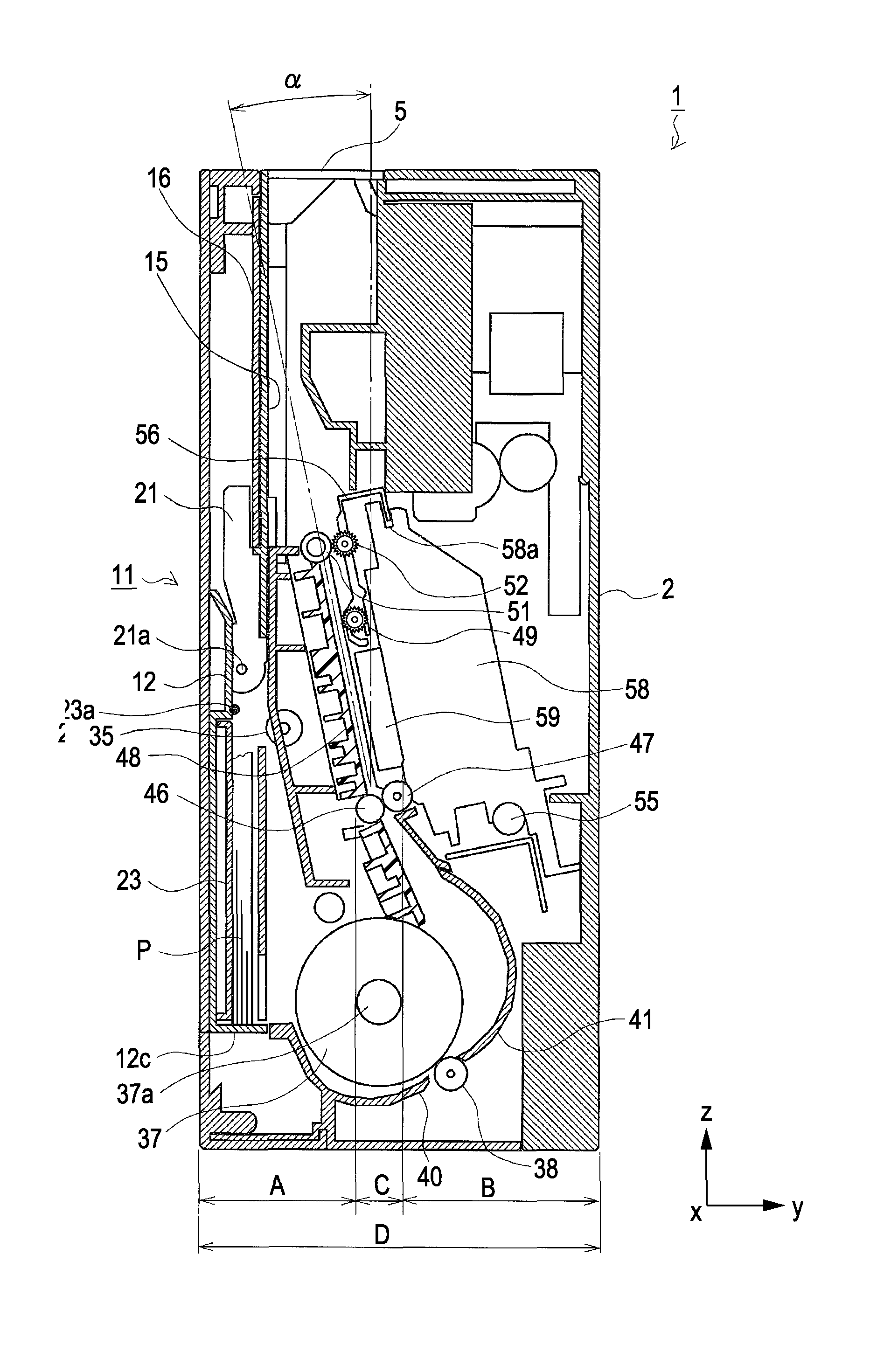
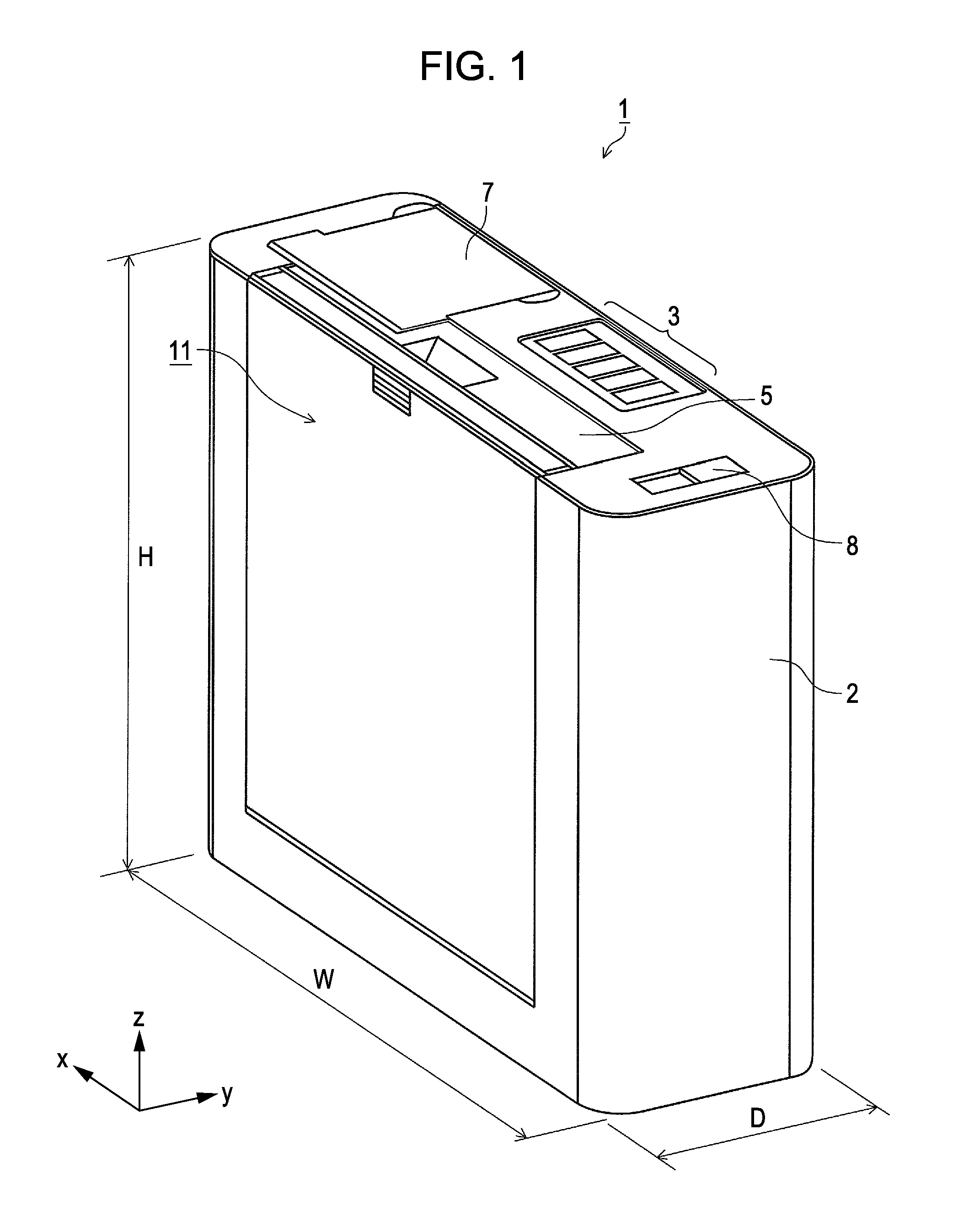
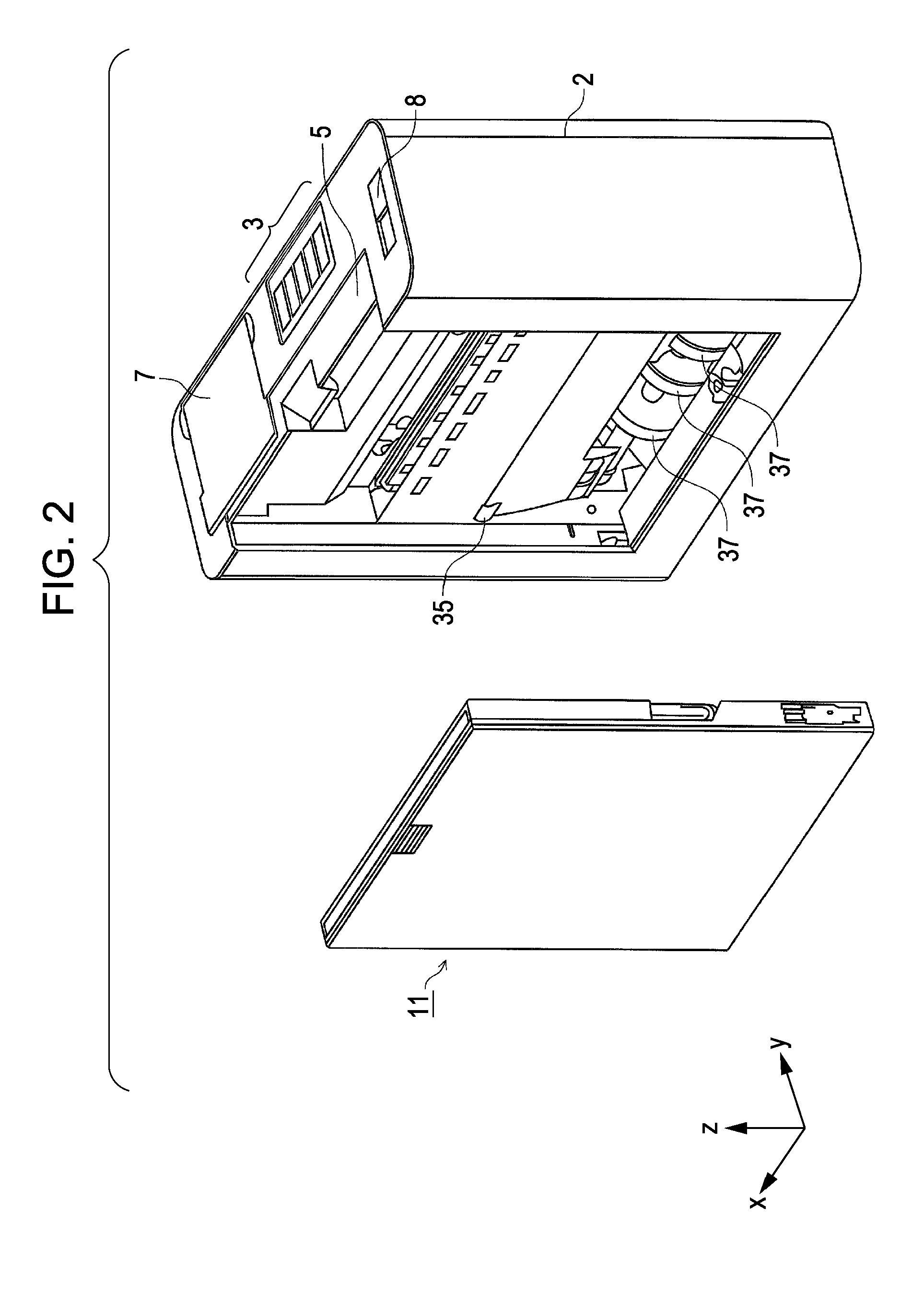
[0033]Hereinafter, an ink jet printer embodying a recording apparatus according to the invention will be described with reference to FIG. 1 through FIG. 9B. FIG. 1 is an overall external perspective view of an ink jet printer 1 according to this embodiment; FIG. 2 is an external perspective view illustrating a state in which a paper cassette 11 has been removed; FIG. 3 is an external perspective view illustrating an upper area of the ink jet printer 1; FIGS. 4 through 6 are cross-sectional views of the same, viewed from the side; FIGS. 7 and 8 are external perspective views of a paper cassette 11 (where FIG. 7 illustrates a state in which an upper cover is closed, and FIG. 8 illustrates a state in which the upper cover is open); and FIGS. 9A and 9B illustrate variations on a paper transport path.

[0034]In order to illustrate the rollers disposed in the paper transport path of the ink jet printer 1, almost all of the rollers are depicted as being aligned with the same surface in FIGS....


PUM


Abstract

A recording apparatus according to the invention includes an ink jet recording head that records onto a recording medium; a paper cassette that holds the recording medium in alignment with the vertical direction; an inverting path unit that inverts the transport direction of the recording medium fed out from the paper cassette; and a downstream-side path unit that transports the recording medium from the inverting path unit toward the paper cassette.

Description

CROSS-REFERENCE TO RELATED APPLICATIONS[0001]Priority is claimed under 35 U.S.C. §119 to Japanese Application Nos. 2010-225040 filed on Oct. 4, 2010 and 2010-225027 filed on Oct. 4, 2010, which are hereby incorporated by reference in their entirety.BACKGROUND[0002]1. Technical Field[0003]The present invention relates to recording apparatuses that record onto a recording medium, and particularly relates to recording apparatuses that include a recording medium transport path in which the recording medium is supplied from a recording medium holding unit, is bent and has its transport direction inverted by an inverting path unit, and is transported toward the top of the apparatus.[0004]2. Related Art[0005]Recording apparatuses such as facsimile devices, printers, and so on employ various types of paper transport paths. Of these, some apparatuses include an approximately U-shaped paper transport path, where the paper is supplied, from a paper cassette that holds the paper, in the vertica...

Claims


Application Information

Patent Timeline
Patent Type & Authority Patents(United States)
IPC IPC(8): B41J2/01
CPCB41J13/10
Inventor KAWABATA, SEIJIKONDO, KATSUYUKITAKESHITA, SANSHIROKOMURO, SHINTARO
Owner SEIKO EPSON CORP
Why Eureka
Try Eureka