High efficiency power generation system and system upgrades

a power generation system and high efficiency technology, applied in the field of high efficiency power generation system and system, can solve the problems of carbon dioxide, a climate changing gas, virtually impossible to economically eliminate in power-generating facilities, coal reduces but not eliminates carbon dioxide, and expensive extraction

Active Publication Date: 2019-04-16
HI EFF UTILITY RESCUE
View PDF16 Cites 9 Cited by
  • Summary
  • Abstract
  • Description
  • Claims
  • Application Information

AI Technical Summary

Problems solved by technology

Burning coal to produce electrical power is one of the critical 21st century power generation dilemmas.
For instance, carbon dioxide, a climate changing gas, is virtually impossible to economically eliminate in power-generating facilities.
The use of natural gas instead of coal reduces, but does not eliminate the carbon dioxide.
Both coal and natural gas also discharge ozone-producing gasses and soot particulates, which are costly to extract from exhaust and flue gas.
The available natural gas stores, however, are much more limited than coal.
The use of natural gas for electrical power generation appears to be misguided in the long term.
Coal extraction, cross country delivery, on site handling and burning can be directly related to human costs, and can be directly related to mounting environmental degradation for just this one plant.
Existing nuclear power plants provide inherent risks, but are engineered and operated to exceptional safety standards.
Satisfying solutions to plant aging are elusive.
Population growth, rising standards of living and economic growth are putting world-wide electrical grid generating capacity margins at risk.
Conservation and alternative generating sources are helpful, but are not expected to meet the growing demand.
In addition, electrical demand growth to power the growing worldwide demand for air conditioning and the anticipated demand for electric cars are projected to further over stress the capacity of existing grids.
Clearly, there is a growing demand for more electrical power, but current methods of power generation are problematic and unsustainable.
However, the continuous, superheated, steam turbine inlet temperature is limited to about 1000 degrees (“°”) Fahrenheit (“F”) to avoid hydrogen embrittlement of the turbine blades.
This material limitation precludes higher efficiencies from operating at higher superheated steam temperatures.
This superheated steam temperature limit exists for both combustion and nuclear heat sources.
The turbine blades and other structures formed of superalloy materials to limit oxidation and creep temperature properties, however, limit turbine operating temperatures to about 2000° to 2100° F. Complex internal turbine blade cooling systems enable turbine inlet gas temperatures to exceed 2500° F., but these high temperatures produce a full range of harmful ozone activators and high levels of nitrous and nitric oxides (“NOx”).
These toxic exhaust products cannot be easily eliminated, and are costly to reduce.
Climate stability-challenging carbon dioxide removal from coal fired boilers is not practical at this time.
In the heating process, the circulating water and steam become radioactive.
This large mass of radioactively contaminated water is an unavoidable and an unfortunate side effect in all existing nuclear power plants.
Another incident occurred at Chernobyl with 31 on-site deaths and long-term evacuation of a 1000 square mile region, plus undisclosed, high human and animal sickness and early deaths.
In 2011, multiple melt downs at the Japanese Fukushima power plants followed a tsunami with monumental tragedies.
Limitations of conventional power generation approaches have now become substantial hindrances for wide-scale power generation with high efficiency and low levels of undesirable environmental pollutants.
No satisfactory strategy has emerged to provide a sustainable, long-term solution for these issues.

Method used


Image

  • High efficiency power generation system and system upgrades
  • High efficiency power generation system and system upgrades
  • High efficiency power generation system and system upgrades

Examples


Embodiment Construction

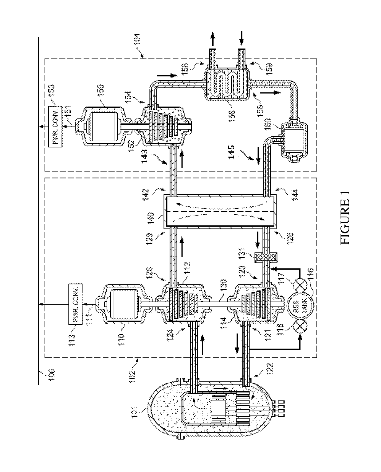
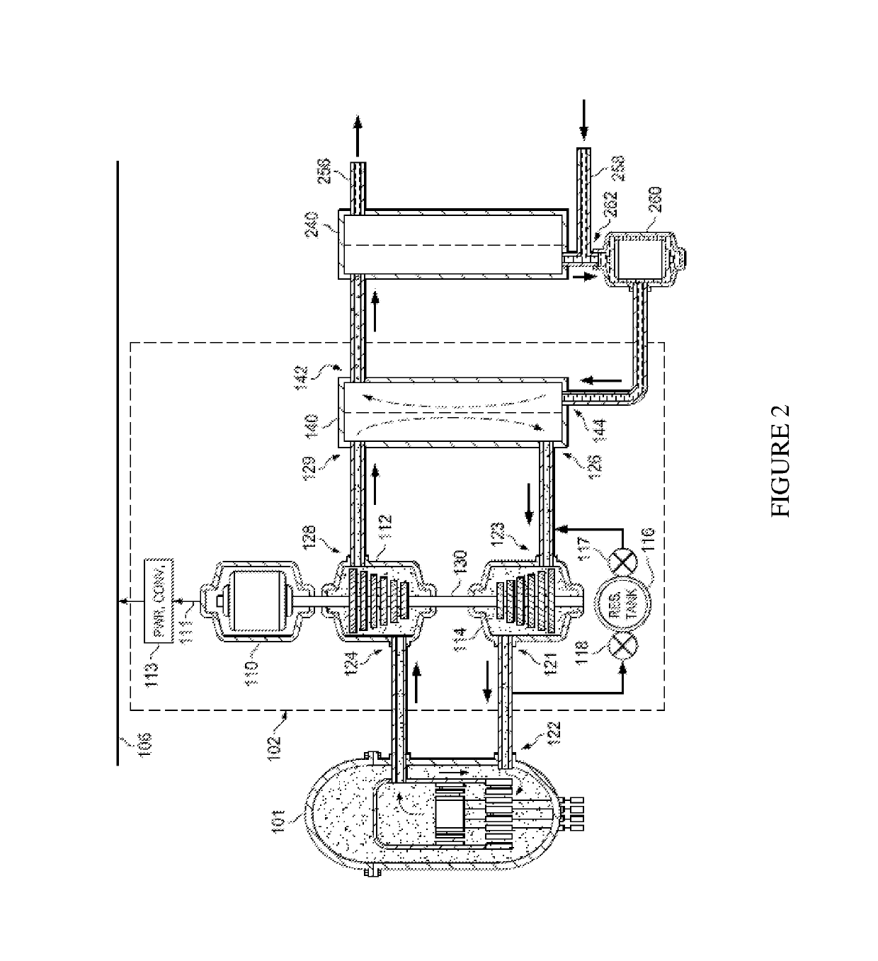
[0026]The making and usage of the present exemplary embodiments are discussed in detail below. It should be appreciated, however, that the embodiments provide many applicable inventive concepts that can be embodied in a wide variety of specific contexts. The specific embodiments discussed are merely illustrative of specific ways to make and use the systems, subsystems and modules associated with a process for producing a thermal power source.

[0027]Combined gas / steam cycle power generation employing open Brayton-closed Rankine combined cycles includes both fuel-burning gas turbine and fuel-burning steam turbine generators. Hot turbine exhaust energy is recovered in a boiler to partially generate steam and superheated steam of a steam power plant. A combined-cycle power generation arrangement, however, requires a full complement of complex and costly components and controls, with full facility costs of both a high performance gas turbine and a complete steam power plant. There remains...


PUM

PropertyMeasurementUnit
pressuresaaaaaaaaaa
temperaturesaaaaaaaaaa

Abstract

A power generation system includes an inert gas power source, a thermal / electrical power converter and a power plant. The thermal / electrical power converter includes a compressor with an output coupled to an input of the inert gas power source. The power plant has an input coupled in series with an output of the thermal / electrical power converter. The thermal / electrical power converter and the power plant are configured to serially convert thermal power produced at an output of the inert gas power source into electricity. The thermal / electrical power converter includes an inert gas reservoir tank coupled to an input of the compressor via a reservoir tank control valve and to the output of the compressor via another reservoir tank control valve. The reservoir tank control valve and the another reservoir tank control valve are configured to regulate a temperature of the output of the thermal / electrical power converter.

Description

[0001]This application is a continuation-in-part of U.S. patent application Ser. No. 14 / 742,760, entitled “High Efficiency Power Generation System and System Upgrades,” filed Jun. 18, 2015, which is a continuation of U.S. patent application Ser. No. 14 / 451,863, entitled “High Efficiency Power Generation System and System Upgrades”, now U.S. Pat. No. 9,068,468, issued Jun. 30, 2015, which is a continuation of U.S. patent application Ser. No. 13 / 971,273, entitled “High Efficiency Power Generation System and System Upgrades,” now U.S. Pat. No. 8,826,639, issued Sep. 9, 2014, which claims the benefit of U.S. Provisional Patent Application Ser. No. 61 / 691,955, entitled “HiEff Mod.” filed on Aug. 22, 2012, which applications are incorporated herein by reference.TECHNICAL FIELD[0002]The present invention is directed, in general, to power generation systems and, more specifically, to a system and method for employing a Brayton closed-cycle power generator to produce electricity and provide ...

Claims


Application Information

Patent Timeline
Patent Type & Authority Patents(United States)
IPC IPC(8): F01K23/02G21D5/08G21C15/28G21C1/02G21C5/12F02C1/05H02K7/18G21D5/06F01K3/18F02C1/06F22B1/18F02C1/08
CPCF02C1/05F01K23/02F02C1/06F02C1/08F22B1/1823G21C1/02G21C5/12G21C15/28G21D5/06G21D5/08H02K7/1823F01K3/181Y10T29/49231Y02E20/16Y02E30/34Y10T29/49229Y02E30/30Y02E30/00
Inventor SIMPKIN, WILLIAM EDWARDWILSON, DONALD R.
Owner HI EFF UTILITY RESCUE
Why Eureka
Try Eureka