
Automatic nut-inserted injection molding system and method of the same

a technology of injection molding system and nut inserting, which is applied in the field of injection molding system, can solve the problems of not meeting the requirements of consistent automation process requirements, labor and cost, and time-consuming process of pressing nuts into the plastic shell, so as to reduce manufacturing cost, reduce labor and cost, and reduce the effect of process

Active Publication Date: 2019-04-23
QUANTA COMPUTER INC
View PDF2 Cites 1 Cited by
  • Summary
  • Abstract
  • Description
  • Claims
  • Application Information

AI Technical Summary

Benefits of technology

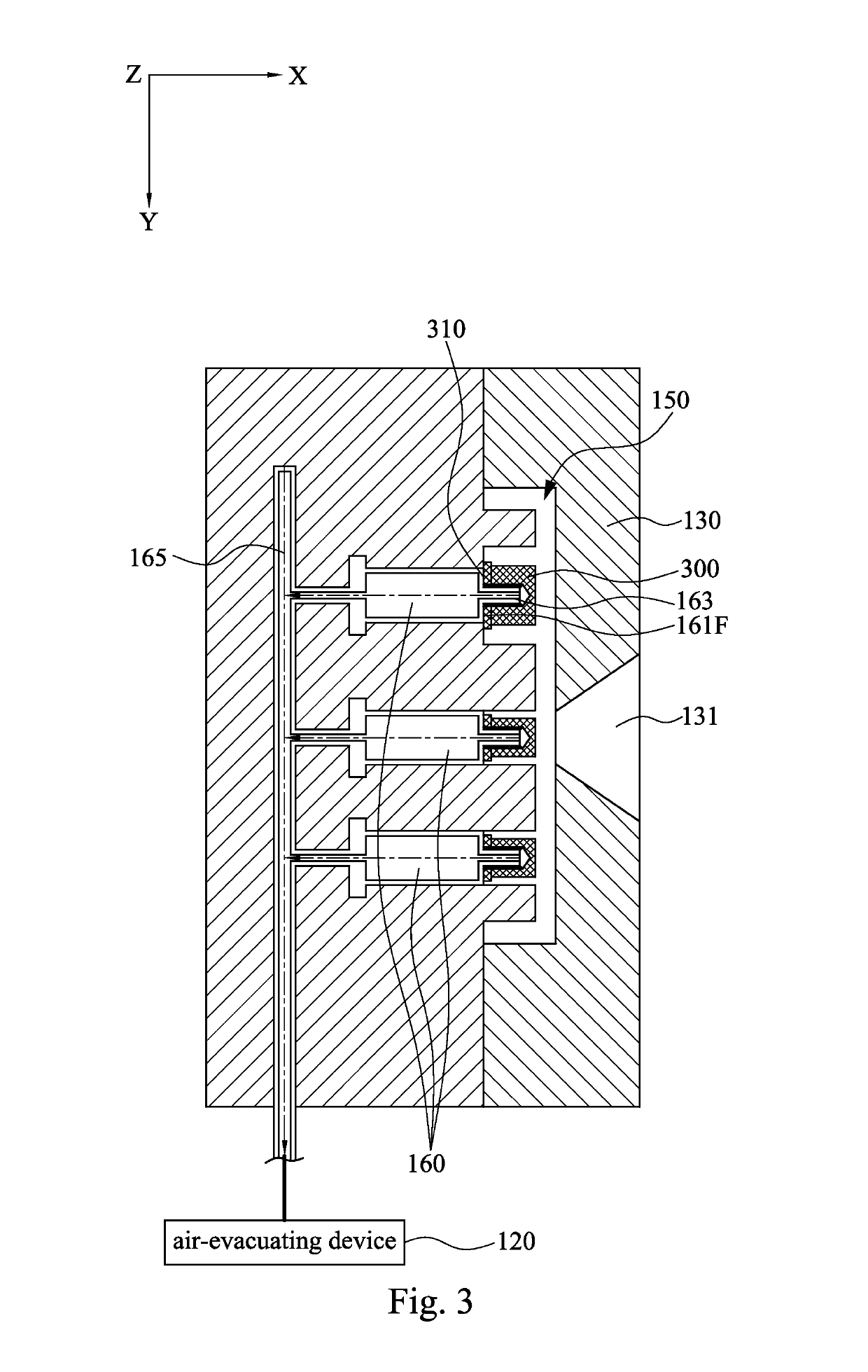
[0008]When the robot arm delivers the nut onto the air needle, so that the air needle inserts into the enclosed nut bore of the nut, the air-evacuating device is activated for drawing air away from the air passage. As the air passage is almost in a vacuum state, the atmospheric pressure in the air passage tightly sucks the nut on an end surface of the second mold block. Thus, as the air-evacuating device draws air of the air passage to generate vacuum attraction, not only the nut can be fixed in the injection-molding module, but also the enclosed nut bore of the nut can be hermetically isolated from the molding cavity so as to avoid resin material in the molding cavity flowing into the enclosed nut bore of the nut.
[0011]Thus, by using the method of automatic nut-inserted injection molding of the disclosure, not only the whole process thereof can be reduced and simplified, but also the step of thermally pressing the heated nuts into the plastic shell can be omitted, and additional time, labor and cost do not required so as to decrease manufacturing cost.

Problems solved by technology

In this regard, the process of pressing the nuts into the plastic shell not only takes time, labor and cost so to be a burden of the production, but also fails to satisfy consistent automation process requirements from injection molding to nut-inserting process.

Method used


Image

  • Automatic nut-inserted injection molding system and method of the same
  • Automatic nut-inserted injection molding system and method of the same
  • Automatic nut-inserted injection molding system and method of the same

Examples


Embodiment Construction

[0021]Reference will now be made in detail to the present embodiments of the disclosure, examples of which are illustrated in the accompanying drawings. Wherever possible, the same reference numbers are used in the drawings and the description to refer to the same or like parts. According to the embodiments, it will be apparent to those skilled in the art that various modifications and variations can be made to the structure of the present disclosure without departing from the scope or spirit of the disclosure.

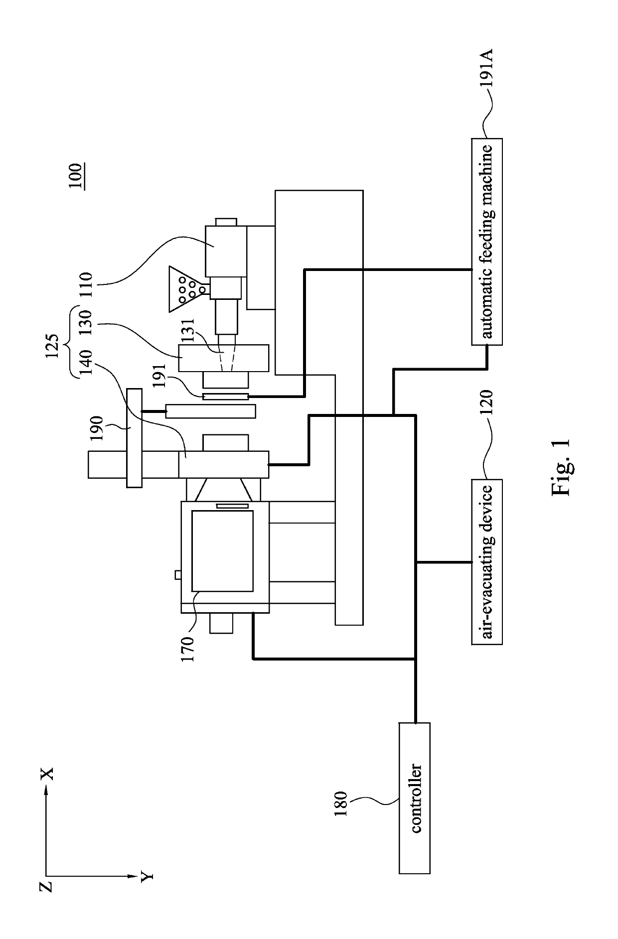
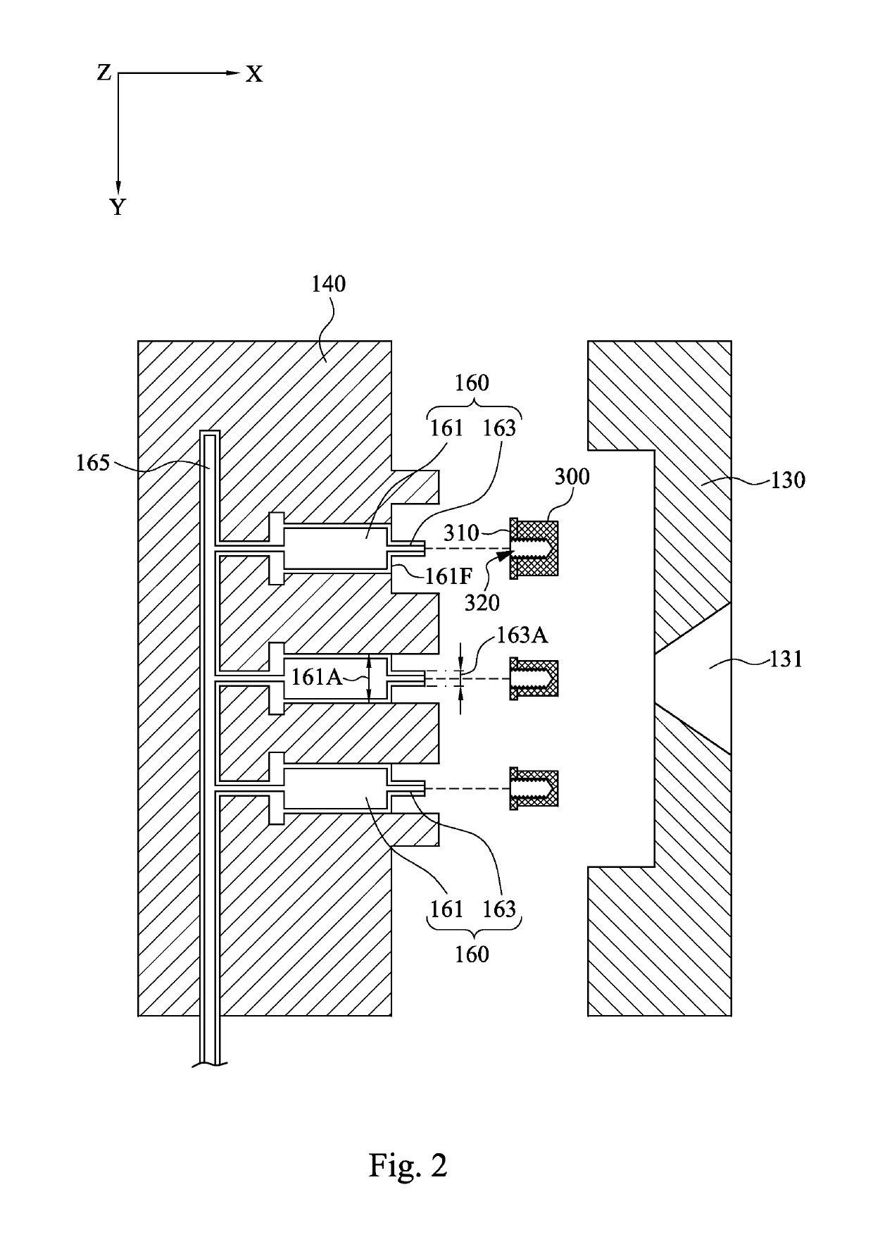
[0022]Reference is now made to FIG. 1 to FIG. 3 in which FIG. 1 is a schematic view of an automatic nut-inserted injection molding system 100 according to an embodiment of this disclosure, FIG. 2 is a schematic view of the first mold block 130 and the second mold block 140 of FIG. 1 in a mold-opening status, and FIG. 3 is a schematic view of the first mold block 130 and the second mold block 140 of FIG. 1 in a mold-closing status. As shown in FIG. 1 to FIG. 3, the automatic nu...


PUM

PropertyMeasurementUnit
internal diameteraaaaaaaaaa
coupling forceaaaaaaaaaa
atmospheric pressureaaaaaaaaaa

Abstract

An automatic nut-inserted injection molding system and a method of the same are provided, and the system includes an automatic feeding machine for providing a nut, an air-evacuating device, a robot arm for delivering the nut, and an injection-molding module. The injection-molding module includes a first mold block, a second mold block, an air passage and an air needle. The second mold block is detachably closed with the first mold block for mutually defining a molding cavity. The air needle is partially embedded in the second mold block. The air passage is formed in the second mold block, and respectively connected to the air needle and the air evacuation device.

Description

RELATED APPLICATIONS[0001]This application claims priority to Taiwan Application Serial Number 104119131, filed Jun. 12, 2015, which is herein incorporated by reference.BACKGROUNDField of Disclosure[0002]The present disclosure relates to an injection molding system and a method of the same. More particularly, the present disclosure relates to an automatic nut-inserted injection molding system and a method of the same.Description of Related Art[0003]In a plastic shell, a plurality of nuts are normally inserted thereon to enhance coupling force of screws and avoid stripped thread of the detached screws, so that assembly parts (e.g., circuited board) can be firmly secured on the nuts of the plastic shell. A traditional process for making the plastic shell having the nuts inserted thereon is, after the formation of the plastic shell, to heat and then press the nuts into the plastic shell, which requires a melting equipment.[0004]In the process of pressing the heated nuts into the plasti...

Claims


Application Information

Patent Timeline
Patent Type & Authority Patents(United States)
IPC IPC(8): B29C45/14B29L1/00
CPCB29C45/14008B29C45/14065B29C2045/14155B29L2001/005
Inventor LIN, SHU-CHEN
Owner QUANTA COMPUTER INC
Learn More