

Angular alignment of optical fibers for fiber optic ribbon cables, and related methods
- Summary
- Abstract
- Description
- Claims
- Application Information
AI Technical Summary
Benefits of technology
Problems solved by technology
Method used
Image

Examples
Embodiment Construction
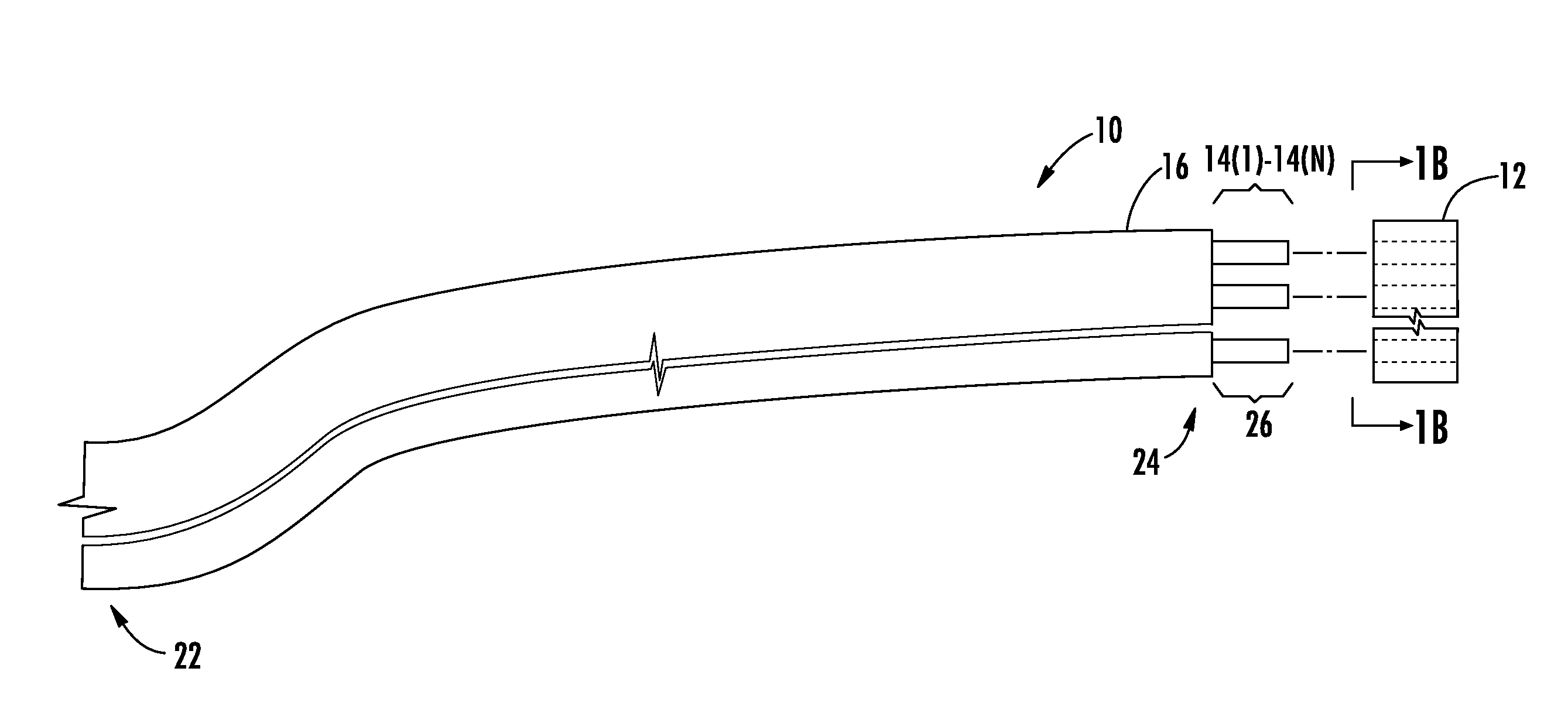
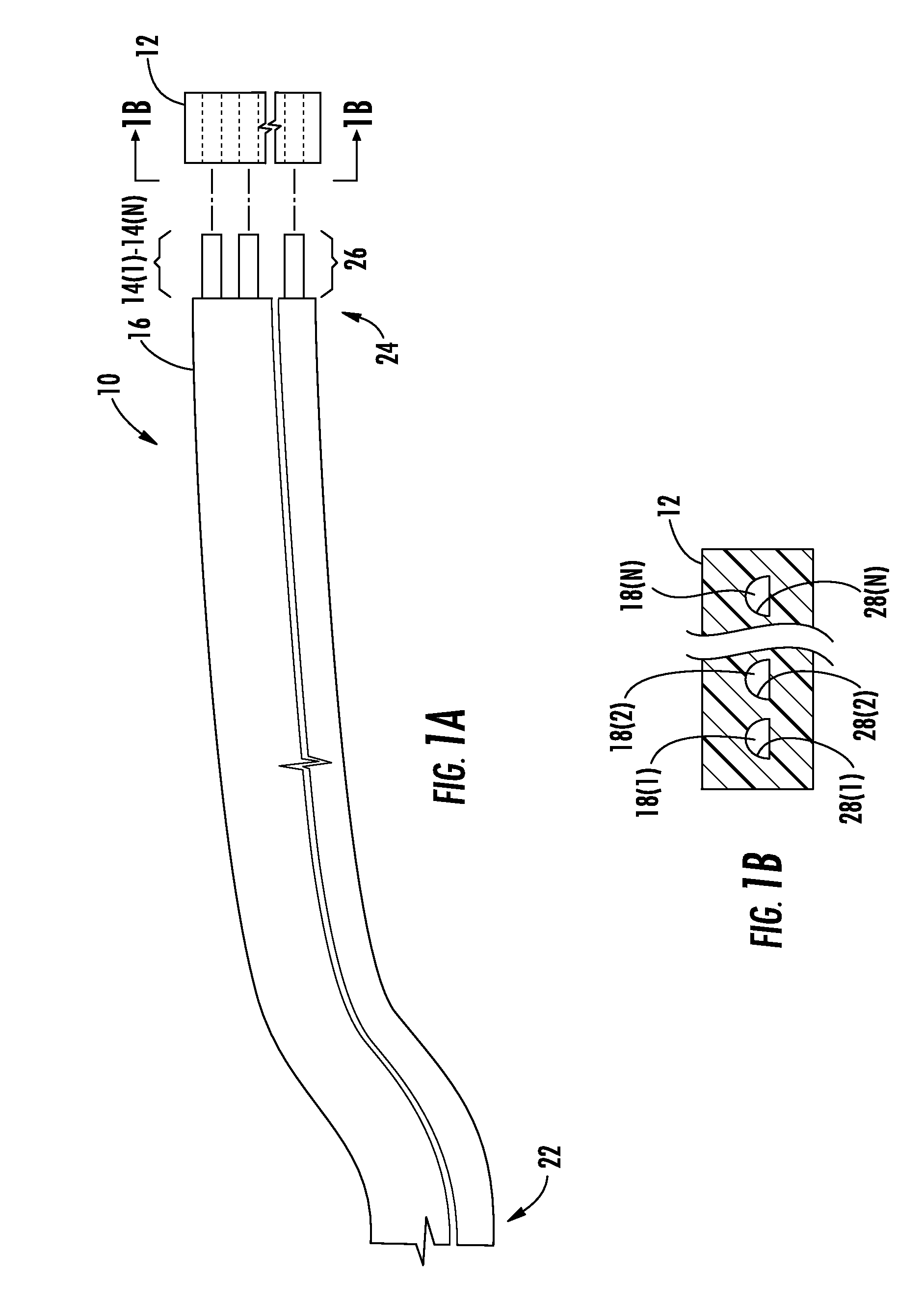
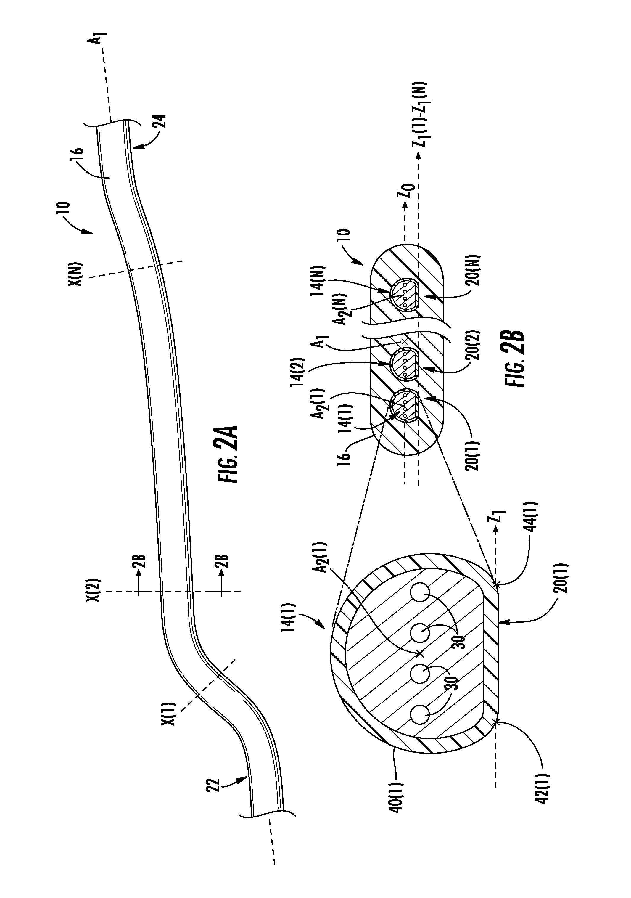
[0009]Embodiments disclosed herein include angular alignment of optical fibers for fiber optic ribbon cables and related methods. Multiple optical fibers disposed in parallel in a ribbon matrix may be used to increase bandwidth between two interconnection points. In this regard, optical fibers are angularly aligned during the process of forming a fiber optic ribbon cable. To angularly align the optical fibers, each of the optical fibers may include an angular alignment feature. The angular alignment feature facilitates uniform or substantially uniform angular orientation along a cable center axis of each of the optical fibers when the optical fibers are prepared to be disposed in the ribbon matrix to form a fiber optic ribbon cable. The uniform or substantially uniform angular orientation may facilitate alignment of each of the optical fibers as part of a process to optically connect each of these optical fibers precisely to a fiber optic connector. The optical fibers are held in an...
PUM
| Property | Measurement | Unit |
|---|---|---|
| Angle | aaaaa | aaaaa |
| Mass | aaaaa | aaaaa |
| Width | aaaaa | aaaaa |
Abstract
Description
Claims
Application Information