Shield end processing structure

a processing structure and shield technology, applied in the direction of coupling protective earth/shield arrangement, connection contact member material, coupling device connection, etc., can solve the problems of inability to achieve peripheral press-clamping, and inability to achieve uniform press-clamping condition. , to achieve the effect of enhancing the efficiency of operation and not increasing the time and labor required for the end processing operation

Active Publication Date: 2008-05-15
YAZAKI CORP
View PDF5 Cites 24 Cited by
  • Summary
  • Abstract
  • Description
  • Claims
  • Application Information

AI Technical Summary

Benefits of technology

[0014]In the invention, there is achieved an advantage that particularly because of the features of the configuration of the shield ring, the end portion of the shielding layer can be fixed uniformly over an entire periphery thereof. In addition, there is achieved an advantage that the end portion of the shielding layer can be held in the good fixed condition. Furthermore, there is achieved an advantage that there can be provided the shield end processing structure in which by fixing the shield shell to the shield ring by inserting the former into the latter, the time and labor required for the end processing operation are not increased as is the case with the conventional structure utilizing the sliding movement.
[0015]In the invention, there is achieved an advantage that the efficiency of the operation can be enhanced.

Problems solved by technology

The above conventional techniques have several problems.
Namely, in the case of the structure of FIG. 3, the end portion of the shielding layer 1 is press-clamped to the shield shell 5 over the entire periphery thereof, and therefore there has been encountered a problem that unless the fixing band 6 is press-fastened to the end portion of the shielding layer 1 over the entire periphery thereof, the uniform press-clamped condition is not obtained.
And besides, the entire-periphery press-fastening can not always be achieved with one press-fastening operation, and this leads to a possibility that the time and labor required for the end processing operation increase.
Thus, the structure of FIG. 4 has the several problems mentioned above.

Method used


Image

  • Shield end processing structure
  • Shield end processing structure
  • Shield end processing structure

Examples


Embodiment Construction

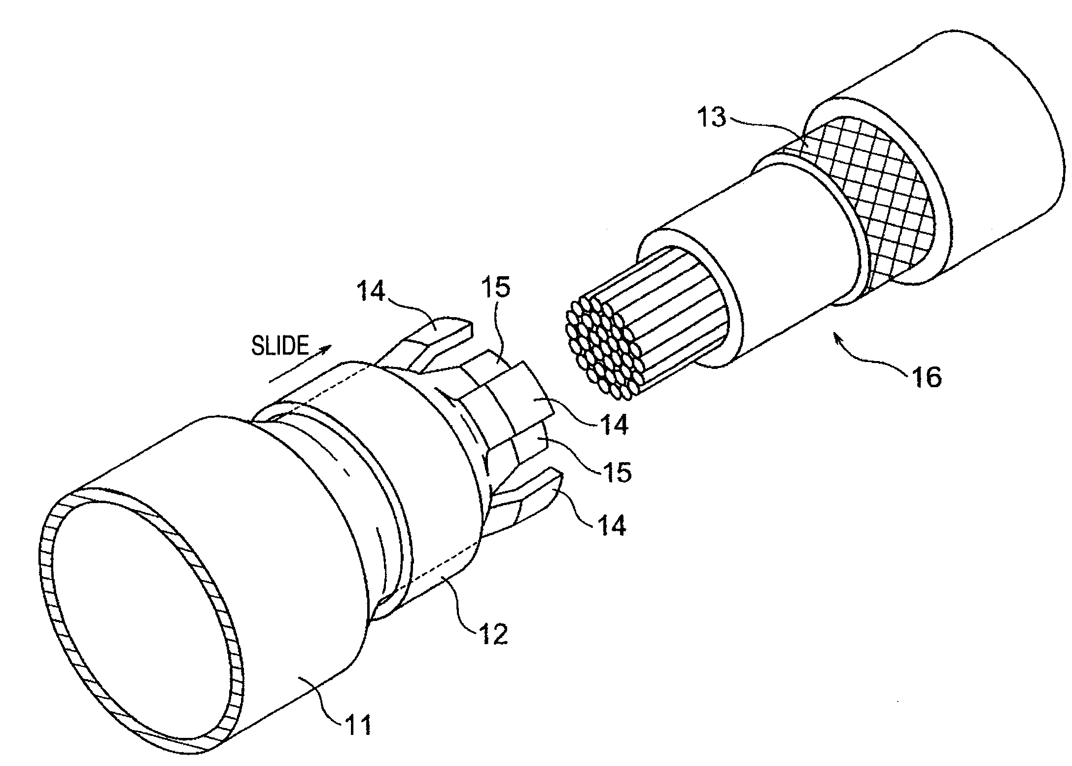
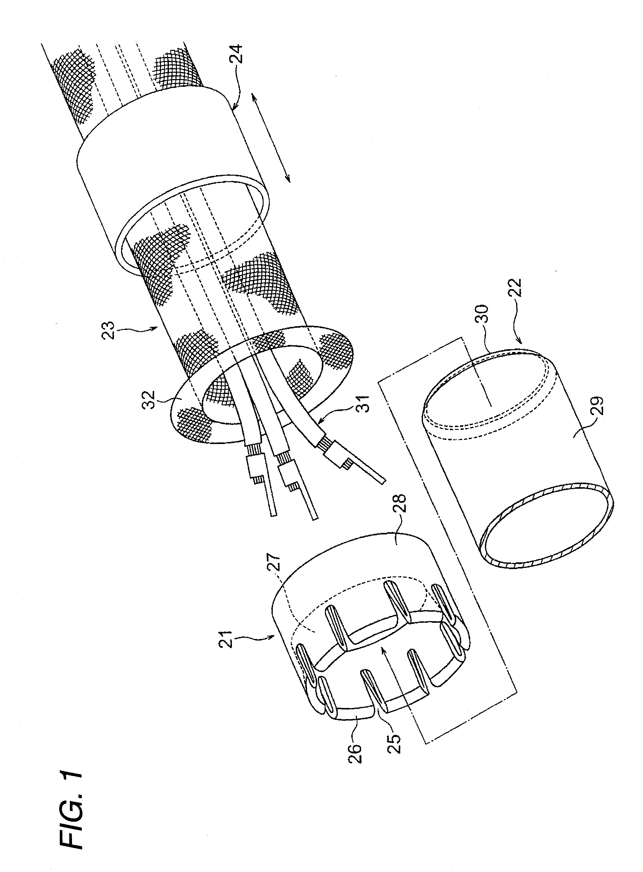
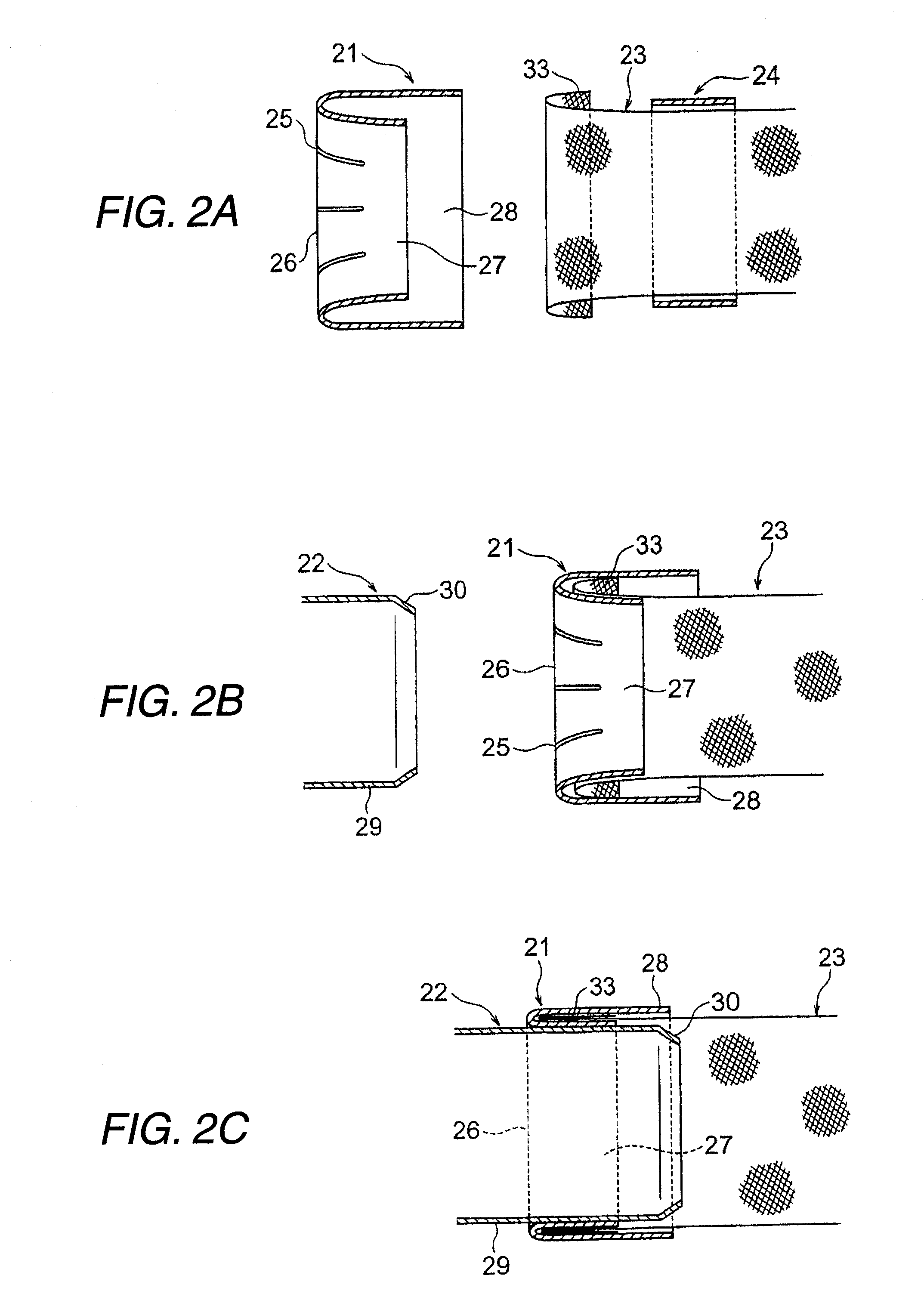
[0020]The present invention will now be described with reference to the drawings. FIG. 1 is an exploded perspective view showing one preferred embodiment of a shield end processing structure of the invention. FIGS. 2A to 2C are views explanatory of an operation for fixing an end portion of a shielding layer.

[0021]In FIG. 1, reference numeral 21 denotes a shield ring made of electrically-conductive metal. Reference numeral 22 denotes a shield shell made of electrically-conductive metal as is the case with the shield ring 21. The shield ring 21 and the shield shell 22 jointly provide a structure (shield end processing structure) in which by inserting the shield shell 22 into an inner periphery of the shield ring 21, the shield ring 21 and the shield shell 22 are fixed to the end portion of the tubular shielding layer 23. Reference numeral 24 denotes a pushing jig 24 of a tubular shape used for inserting the end portion of the shielding layer 23 into the shield ring 21. The constituent...


PUM


Abstract

An end portion of a shielding layer is inserted between an inner tubular portion and an outer tubular portion of a shield ring by the use of a tubular pushing jig, and in this condition when a shield shell is inserted into the shield ring in a direction opposite to the direction of inserting of the shielding layer, the shield ring is pressed by the shield shell, so that a gap between the inner tubular portion and the outer tubular portion decreases, and the shielding layer is firmly held between the inner and outer tubular portions, thereby achieving a fixed condition of the shielding layer. Namely, the shield ring and the shield shell are fixed to the end portion of the shielding layer.

Description

BACKGROUND OF THE INVENTION[0001]1. Field of the Invention[0002]This invention relates to a shield end processing structure in which a shield shell and a shield ring each having electrical conductivity are fixed to an end portion of a tubular shielding layer[0003]2. Related Art[0004]For example, in an electric car or a hybrid car, it is known that electromagnetic waves are generated from a large-current / high-voltage power cable (or wire) connected to a motor mounted on such a vehicle. Therefore, it has been important to provide electromagnetic shielding means which can prevent adverse effects of such electromagnetic waves and also can also prevent adverse effects of electromagnetic waves from the exterior. With respect to the electromagnetic shielding means, the following technique is disclosed in JP-A-2003-115223 Publication mentioned below.[0005]In FIG. 3, reference numeral 1 denotes a shielding layer (braid) formed by interweaving electrically-conductive metal wire elements into ...

Claims


Application Information

Patent Timeline
Patent Type & Authority Applications(United States)
IPC IPC(8): H01R9/03
CPCH01R9/0527H02G15/064H02G3/0666
Inventor HAMAI, TSUYOSHINAGAO, AKIHIRO
Owner YAZAKI CORP
Why Eureka
Try Eureka