Angle estimating method and radar system

a radar system and angle estimation technology, applied in the direction of instruments, measurement devices, using reradiation, etc., can solve the problems of reducing the accuracy of doa estimation, enlarge the disposing space, and the error of estimated angles in different degrees, so as to increase the disposing area of antennas and enhance angle estimation accuracy.

Active Publication Date: 2019-04-23
WISTRON NEWEB
View PDF5 Cites 1 Cited by
  • Summary
  • Abstract
  • Description
  • Claims
  • Application Information

AI Technical Summary

Benefits of technology

[0007]It is therefore a primary objective of the present invention to provide an angle estimation method and a radar system capable of enhancing angle estimation accuracy without increasing disposing area of antenna, to improve over disadvantages of the prior art.

Problems solved by technology

Otherwise, the estimated angle may have an error in different degree.
That is, different angles may correspond to a same phase difference, which may degrade an accuracy of DOA estimation.
However, including more antennas and increasing the distances between the antennas would enlarge the disposing space for the radar system, which is not good for the vehicular radar system.

Method used


Image

  • Angle estimating method and radar system
  • Angle estimating method and radar system
  • Angle estimating method and radar system

Examples


Embodiment Construction

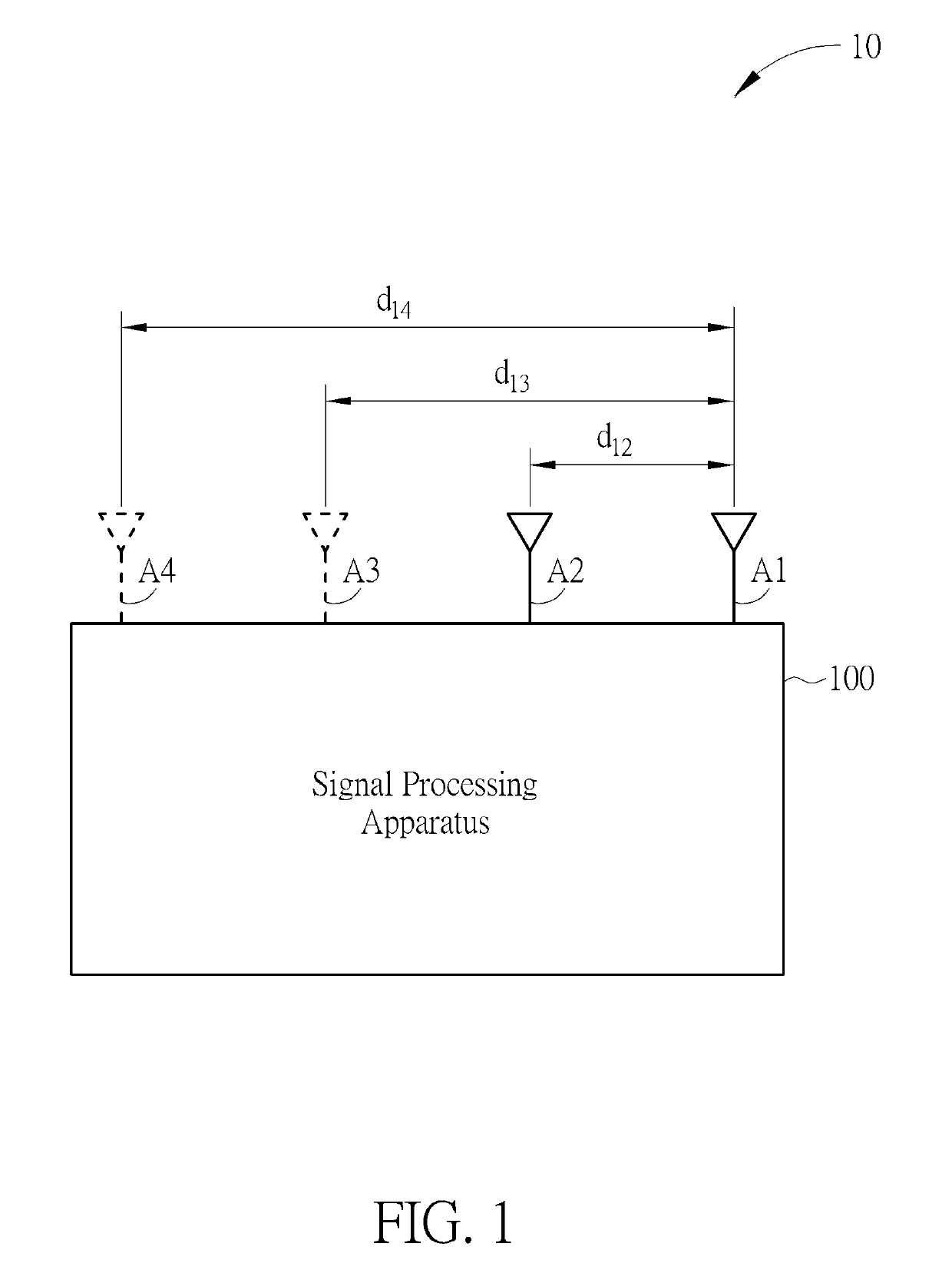
[0018]FIG. 1 is a schematic diagram of a radar system 10 according to an embodiment of the present invention. The radar system 10 comprises physical antennas (A1 and A2), virtual antennas (A3 and A4), and a signal processing apparatus 100. The antennas A1˜A4 form as an antenna array. The antennas A2, A3, A4 have distances d12, d13, d14 relative to the antenna A1. The antennas A1˜A4 are linearly arranged with equal spacing, i.e., the distance d13 between the antennas A1 and A3 is twice of the d12, and the distance d14 between the antennas A1 and A4 is three times of the distance d12. The antennas A1˜A4 are configured to receive signals y1˜y4 reflected from a target object. The antennas A1˜A4 are coupled to the signal processing apparatus 100. The signal processing apparatus 100 computes a direction of arrival (DOA) θ, which is a DOA of the target object, according to the signals y1˜y4. Specifically, the signal processing apparatus 100 computes phase differences φ12, φ13 and φ14 of th...


PUM


Abstract

An angle estimating method applied in a radar system includes receiving a first signal and a second signal reflected from a target object via a first antenna and a second antenna; obtaining a first phase difference and at least one virtual phase difference, where the first phase difference is a phase difference between the first antenna and the second antenna; and obtaining a direction of arrival (DOA) of the target object according to the first phase difference and the at least one virtual phase difference.

Description

BACKGROUND OF THE INVENTION[0001]1. Field of the Invention[0002]The present invention relates to an angle estimation method and a radar system, and more particularly, to an angle estimation method and a radar system capable of enhancing angle estimation accuracy.[0003]2. Description of the Prior Art[0004]Phase impulse radar systems are usually equipped with one transmit antenna and two receive antennas. The radar system estimates an angle / direction of arrival (DOA) of a target object via a time difference of signals received by the different receive antennas. Specifically, the radar system may generate the phase difference corresponding to the time difference of received signals from different antennas. Since the phase difference and the DOA of the target have a specific corresponding relationship, after the radar system obtains the phase difference of the received signals from different antennas, the radar system may compute the DOA of the target object. An accuracy of angle estima...

Claims


Application Information

Patent Timeline
Patent Type & Authority Patents(United States)
IPC IPC(8): G01S13/06H01Q21/08G01S13/93G01S13/00G01S13/02G01S13/931
CPCG01S13/06G01S13/931H01Q21/08G01S13/003G01S2013/0263
Inventor KUO, CHI-CHENGHSIAO, HSIN-LUNGLI, JENG-DA
Owner WISTRON NEWEB
Why Eureka
Try Eureka