Hair brush

a hair brush and brush head technology, applied in the field of hair brushes, can solve the problems of inconvenient use, different hair brushes suffer from different disadvantages, and brushes tend to be non-durable,

Active Publication Date: 2019-04-30
TUNG HING PLASTIC MFR LTD
View PDF13 Cites 6 Cited by
  • Summary
  • Abstract
  • Description
  • Claims
  • Application Information

AI Technical Summary

Benefits of technology

[0005]According to a first aspect of the present invention, there is provided a method of manufacture of a hair brush comprising the steps of providing a base member having connection means at a circumferential region thereof, providing a sheet material having a plurality of spikes extending from an outwardly facing surface of the sheet material, the sheet material and the spikes being integrally formed by injection molding of a plastic(s) material selected from the group of thermoplastics polyester elastomer (TPE-E), polyether block amide copolymer (TPE-A), thermoplastic polyurethane (TPU) and polyurethane (PU), with a hardness from substantially Shore D50 to D65, and with a flexural modulus from 30,000 PSI to 40,000 PSI, assembling the sheet material by fitting perimeter thereof to the circumferential region of the base member, the base member and the connection means being configured to allow the sheet material to secure to the base member, wherein, in an assembled configuration, the outwardly facing surface assumes a convex curvature, and a cavity is defined between the sheet material and the base member, such that in use when the spikes are under pressure the spikes are movable in response to the pressure, causing corresponding movement to the sheet material, the movement creating a cushioning effect.

Problems solved by technology

While cushion brushes generally are useful, different hair brushes suffer from different disadvantages.
Some hair brushes tend to be non-durable due to its inherent physical structure, while other hair brushes are complex in their construction such that manufacturing thereof are costly and inefficient.

Method used


Image

  • Hair brush
  • Hair brush
  • Hair brush

Examples


Embodiment Construction

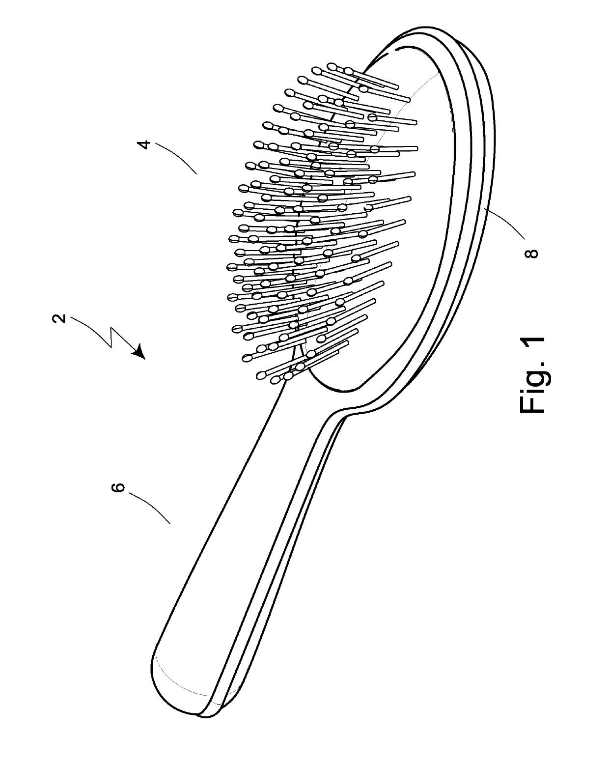
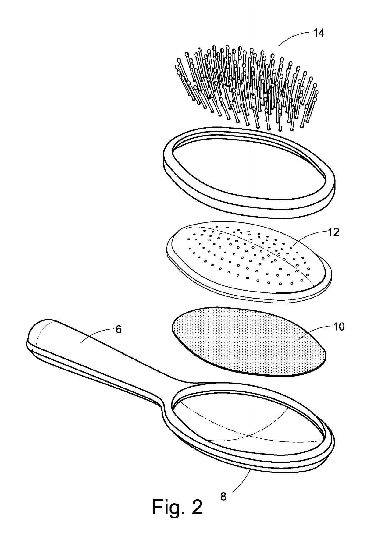
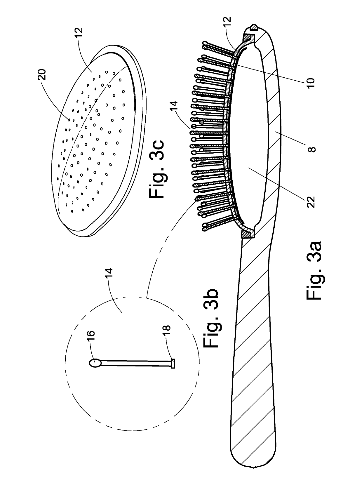
[0027]FIGS. 1 to 3a show a prior art hair brush 2. FIG. 2 shows the various components of the hair brush. In particular, the hair brush comprises a utility portion 4 at a front end and a handle portion 6 at the rear end or opposite end. The utility portion 4 has a brush body having a base member 8 from which the handle portion 6 extends. The brush body further includes a supporting membrane 10, a sheet material 12 and a plurality of bristles 14. The bristles 14 have rounded upper end 16 and enlarged lower end 18 resembling a nail head. The sheet material 12 is provided with a number of apertures 20 through which the bristles 14 protrude away from the base member 8. During manufacturing, the bristles 14 are assembled with the sheet material 12 by implanting or shooting the bristles 14 through the sheet material 12 such that majority length of the bristles 14 extend away from the base member 8. After the assembly, the lower end 18 of the bristles 14 protrude slightly through the sheet...


PUM

PropertyMeasurementUnit
hardnessaaaaaaaaaa
flexural modulusaaaaaaaaaa
pressureaaaaaaaaaa

Abstract

One aspect of the present invention is concerned with a method of manufacture of a hair brush. The method has the steps of providing a base member having connection means at circumferential region thereof, providing a sheet material having a plurality of spikes extending from outwardly facing surface of the sheet material, the sheet material and the spikes are integrally formed by injection molding of a plastic(s) material selected from the group consisting of thermoplastics polyester elastomer (TPE-E), polyether block amide copolymer (TPE-A), thermoplastic polyurethane (TPU) and polyurethane (PU), with a hardness from substantially Shore D50 to D65, and with a flexural modulus from 30,000 PSI to 40,000 PSI, assembling the sheet material by fitting perimeter thereof to the circumferential region of the base member, the base member and the connection means are configured to allow the sheet material to secure to the base member. The outwardly facing surface assumes a convex curvature. In an assembled configuration, a cavity is defined between the sheet material and the base member. In use, when the spikes are under pressure the spikes are movable in response to the pressure, causing corresponding movement to the sheet material, the movement creating a cushioning effect.

Description

CROSS REFERENCE TO RELATED APPLICATION[0001]This application is filed with a claim of priority from GB Patent Application No. 1421635.2 filed Dec. 4, 2014, contents of which are incorporated in this application in their entirety.FIELD OF THE INVENTION[0002]The present invention is concerned with a hair brush, and in particular an improved hair brush also known as cushion brush in the field of invention.BACKGROUND OF THE INVENTION[0003]There are many types of hair management tools in the market to suit different needs of users. One particular type of such tools is cushion brush. While cushion brushes generally are useful, different hair brushes suffer from different disadvantages. Some hair brushes tend to be non-durable due to its inherent physical structure, while other hair brushes are complex in their construction such that manufacturing thereof are costly and inefficient.[0004]The present invention seeks to address such problems, or at least to provide an alternative to the publ...

Claims


Application Information

Patent Timeline
Patent Type & Authority Patents(United States)
IPC IPC(8): A46B3/20A46B3/04B29C45/00A46B9/02A46B3/00B29K21/00B29K67/00B29K75/00B29K77/00B29L21/00
CPCA46B3/20A46B3/005A46B3/04A46B9/023B29C45/0001B29L2021/00B29K2067/00B29K2075/00B29K2077/00B29K2995/007B29K2995/0082B29K2021/003A45D24/04A46B7/00A46D1/0207B29C45/00A46B2200/104A46B5/0025A46B5/0029A46B5/0037A46B9/026A46D1/00
Inventor SZE, KA CHUEN
Owner TUNG HING PLASTIC MFR LTD
Why Eureka
Try Eureka