Reusable packaging and storage

a technology for applied in the field of reusable packaging and storage articles, can solve the problems of cleaning and keeping clean

Active Publication Date: 2019-04-30
RECKITT BENCKISER HEALTH LTD
View PDF15 Cites 5 Cited by
  • Summary
  • Abstract
  • Description
  • Claims
  • Application Information

AI Technical Summary

Benefits of technology

[0007]The point at which the pillar is provided with a diameter equal to the diameter of the of the central aperture of the elastic constriction ring is hereinafter termed the impingement point and is the point at which, in use, an inner surface of the aperture in the elastic constriction ring makes contact with the pillar to secure the ring in frictional engagement with the pillar. Preferably the pillar is configured with the impingement point being located on the pillar such that, in use, a bottom surface of the elastic constriction ring is suspended above an upper surface of the cavity of the bottom member. This arrangement may be advantageous as it can promote airflow around a portion of the ring to permit effective drying thereof post-cleaning.
[0010]The perimeter lip of the bottom member is preferably at the same height or closer to the base of the cavity than the impingement point. This arrangement may be advantageous as, in use, when the top member and bottom member are disengaged from each other, the article is in the open position, the ring is held on the pillar by frictional force at the impingement point and the low height of the perimeter lip of the bottom member presents a large surface area of the ring thus making it easier user for a user to grab the ring and remove same from the pillar.
[0014]The top member and / or bottom member may be provided with one or more vent holes. The vent holes may be advantageous to allow moisture to drain away from the ring post-cleaning.

Problems solved by technology

Elastic constriction rings are typically intended to be reused and therefore they can be problematic to clean and keep clean after their first use until subsequent re-use.

Method used


Image

  • Reusable packaging and storage
  • Reusable packaging and storage

Examples


Embodiment Construction

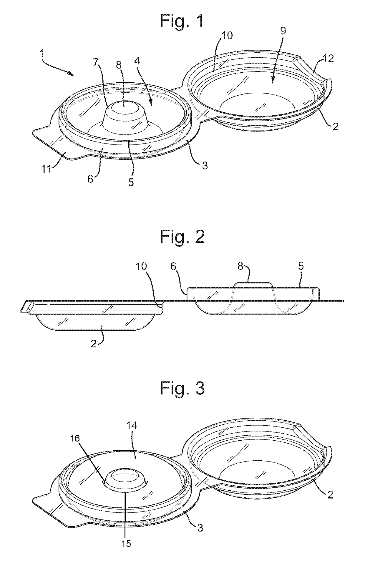
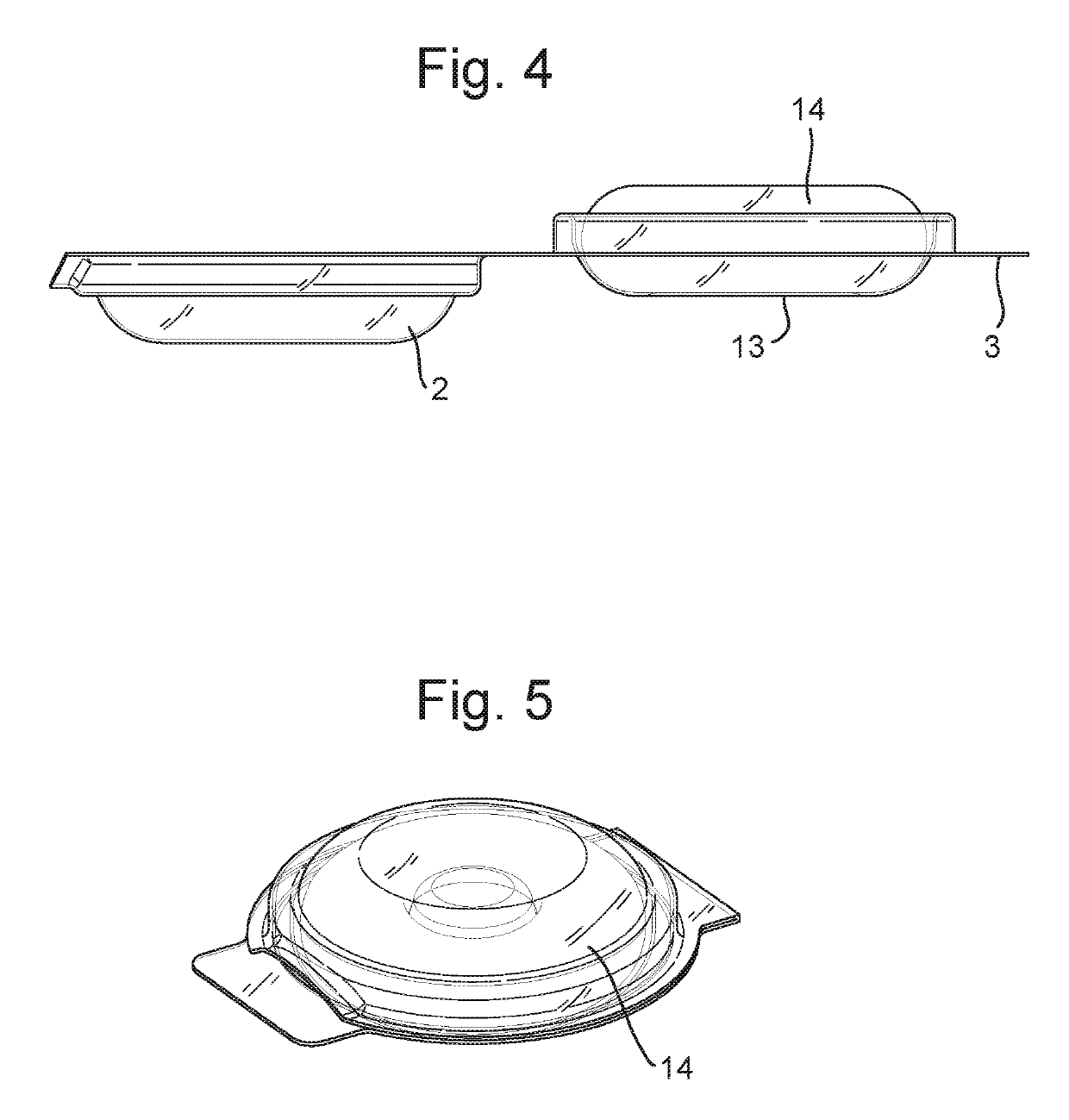
[0027]FIGS. 1&2 illustrate a reusable packaging and storage article 1 suitable for packaging and storing an elastic constriction ring 14. The article 1 is made in one-piece having a top member 2 and a bottom member 3. The bottom member 3 has a cavity 4 of substantially tubular circular shape. At the perimeter of the cavity 4 is a perimeter lip 5 which has a flat outer surface 6. From a substantially central portion of the cavity extends a pillar 7. The pillar 7 is at least partially conical and is shown as frusto-conical with the widest part of the pillar 7 being adjacent a base of the cavity 4 and culminating in a flat summit 8. As can be seen in FIG. 2 the summit 8 has a greater height than the height of the perimeter wall 5.

[0028]The top member 2 is provided with a cavity 9 having a circular shape which is configured to accommodate a proportion of the elastic constriction ring 14 and pillar 7. The cavity 9 is provided with a perimeter lip 10 having a flat inner surface. The diame...


PUM

PropertyMeasurementUnit
resilient elasticaaaaaaaaaa
shapeaaaaaaaaaa
perimeteraaaaaaaaaa

Abstract

A reusable packaging and storage article for an elastic constriction ring is described wherein the article comprises a top member and a bottom member configured to releasably engage with each other, wherein the bottom member comprises: a cavity of substantially circular shape having a perimeter lip with an inner and outer surface to house, in use, a portion of the elastic constriction ring; and an at least partially pillar extending from a substantially central portion of the cavity; and wherein a summit of the pillar has a diameter less than the diameter of a central aperture of the elastic constriction ring, and a lower portion of the pillar has a diameter greater than the diameter of a central aperture of the elastic constriction ring; and wherein the top member comprises: a cavity of substantially circular shape having a perimeter lip with an inner and outer surface to house, in use, a portion of the elastic constriction ring, wherein the diameter of an inner surface of the perimeter is the same or greater than the diameter of the outer surface of the perimeter lip of the bottom member. A consumer product is also described.

Description

FIELD OF THE INVENTION[0001]The invention relates to a reusable packaging and storage article and particularly, but not exclusively, a reusable packaging and storage article for the packaging and storage of an elastic constriction ring.BACKGROUND[0002]It is well known that providing a constriction at the base of a penis helps to maintain a longer and firmer erection and, to this end, elastic constriction rings are commonly used to facilitate such a constriction. Elastic constriction rings are typically intended to be reused and therefore they can be problematic to clean and keep clean after their first use until subsequent re-use.[0003]The reusable packaging and storage article is intended to address such drawbacks.SUMMARY OF INVENTION[0004]According to a first aspect of the present invention there is provided therefore a reusable packaging and storage article for an elastic constriction ring comprising a top member and a bottom member configured to releasably engage with each other...

Claims


Application Information

Patent Timeline
Patent Type & Authority Patents(United States)
IPC IPC(8): B65D1/24B65D51/16B65D43/02A61F5/41A61F6/00B65D43/16B65D75/32B65D85/07
CPCB65D1/24A61F5/41A61F6/005B65D43/0214B65D51/16B65D75/326B65D43/162Y02W30/807A61F2005/414B65D11/02B65D25/02B65D85/02Y02W30/80B65D85/07B65D11/105B65D43/16B65D43/161B65D81/05B65D81/113B65D81/133B65D85/04
Inventor PAN, KEVINZABORNIAK, PIOTRVAN WETTEN, TEUN FRANCISCUS
Owner RECKITT BENCKISER HEALTH LTD
Why Eureka
Try Eureka