Method and system for three-dimensional imaging

a three-dimensional imaging and system technology, applied in the field of three-dimensional (3d) imaging, can solve the problems of bringing in extra computing time, affecting the accuracy of three-dimensional reconstruction, and requiring considerable computing time, so as to achieve more efficient and accurate 3d reconstruction.

Active Publication Date: 2019-05-07
DENTAL IMAGING TECH
View PDF21 Cites 0 Cited by
  • Summary
  • Abstract
  • Description
  • Claims
  • Application Information

AI Technical Summary

Benefits of technology

[0006]It is accordingly an object of the invention to provide a method and system for providing real-time feedback for three-dimensional imaging procedure during the free capture of individual 3D views with handheld scanning devices, which overcomes the above-mentioned disadvantages within the known devices of this general type and which enables more efficient and accurate 3D reconstructions.
[0009]The present invention provides directly perceivable feedback on the location of the previously acquired 3D view relative to a new 3D view to be captured, so that the user may be fully aware if the place he or she locates the scanning device for the new 3D view is appropriate for 3D modeling. The feedback is based on the tracking of two-dimensional images in the viewfinder of the scanning device corresponding to the 3D views. Since the feedback is independent of any stitching algorithm in three-dimensional space, the present invention does not introduce noticeable processing cost and time increase. Rather, with the operator of the scanning device knowing where to conduct an effective scan, the 3D stitching process may be substantially enhances, in terms of both speed and quality.

Problems solved by technology

For the handheld 3D camera or scanning device products which allow the user to operate freely, i.e. to collect three-dimensional views of the object from substantially random orientations or positions relative to the object, there may exist particular difficulties for the stitching process since a randomly captured view could only mislead the reconstruction, bringing extra burden on calculation rather than a desired result.
Rather, the operator shall use his or her own judgment on site, and it is often the case that with more scans being conducted, considerable computing time may be required, while the results might often be inaccurate.

Method used


Image

  • Method and system for three-dimensional imaging
  • Method and system for three-dimensional imaging
  • Method and system for three-dimensional imaging

Examples


Embodiment Construction

[0027]While the invention covers various modifications and alternative constructions, embodiments of the invention are shown in the drawings and will hereinafter be described in detail. However it should be understood that the specific description and drawings are not intended to limit the invention to the specific forms disclosed. On the contrary, it is intended that the scope of the claimed invention includes all modifications and alternative constructions thereof falling within the scope of the invention as expressed in the appended claims.

[0028]Unless defined in the context of the present description, otherwise, all technical and scientific terms used herein have the same meaning as commonly understood by one of ordinary skill in the art to which this invention belongs.

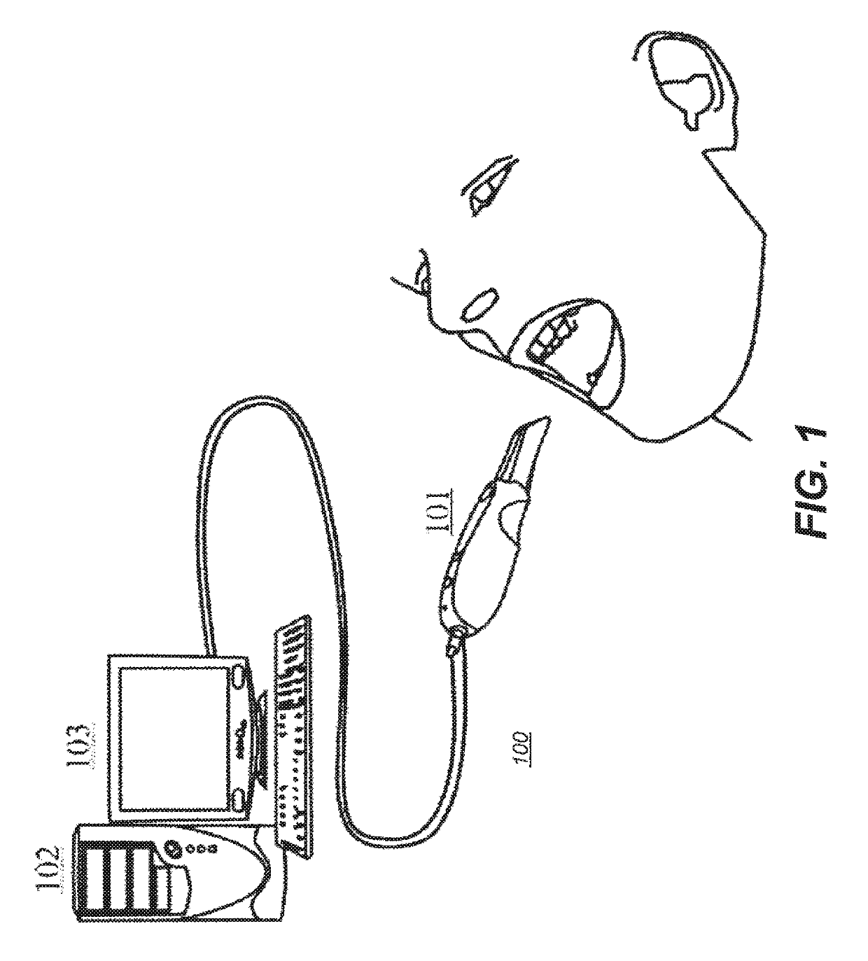
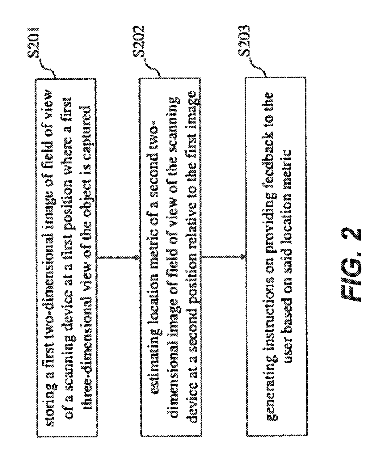
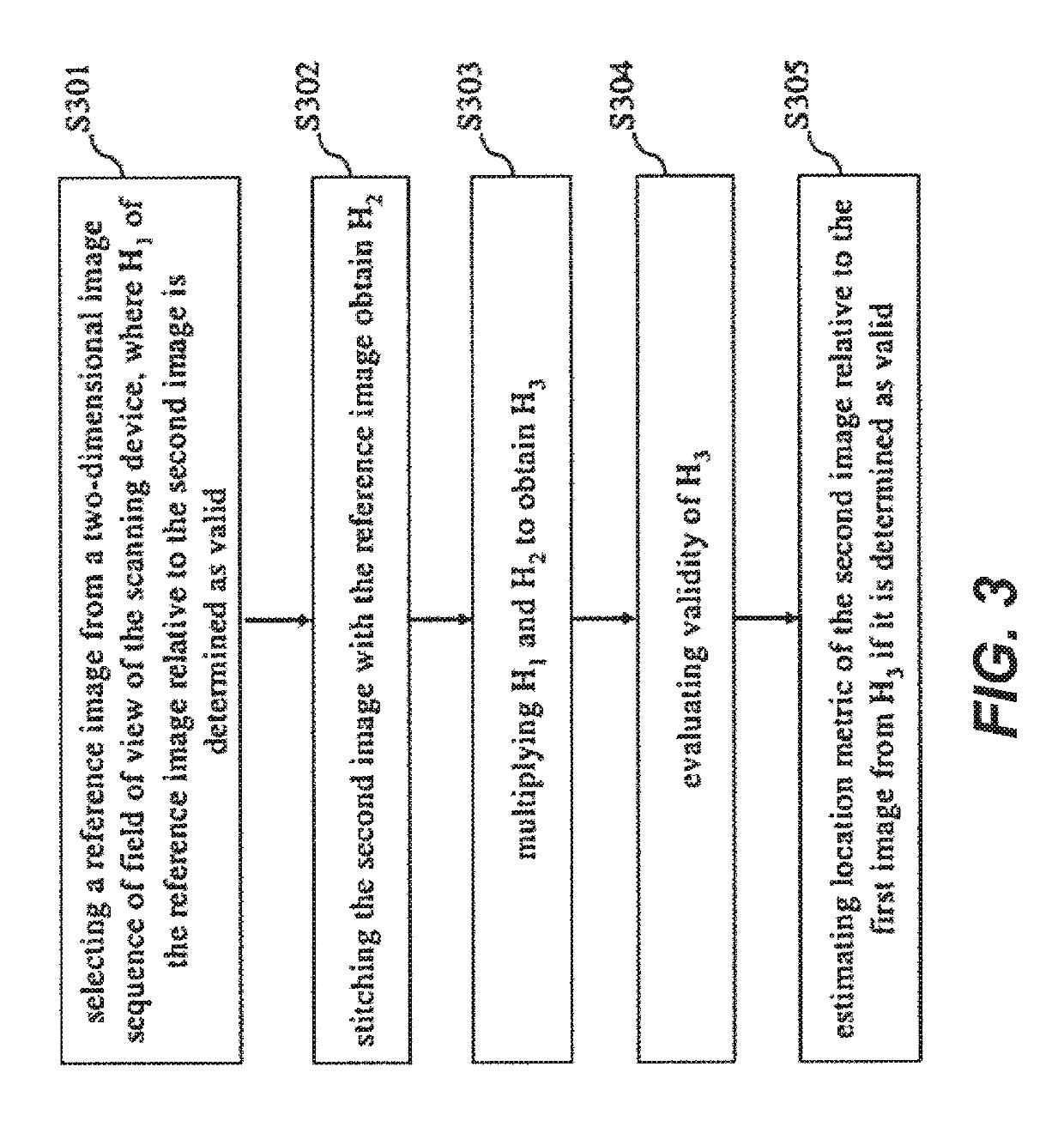
[0029]It is described below a technique for providing real-time feedback to a user operating a three dimensional scanning device for three-dimensional imaging. However, it will be appreciated that the inventive co...


PUM


Abstract

A method for three-dimensional imaging stores a first image of field of view from a handheld optical coherence tomography (OCT) scanning device at a first position where a first OCT scan of an object is captured with the scanning device freely operated by a user. A location metric of a second image of field of view of the scanning device is estimated at a second position relative to the first image while the scanning device is moved from the first to the second position. Instructions on providing user feedback are generated based on the location metric. Feedback is provided to indicate if the second position is adequate for a second OCT scan, wherein providing feedback includes providing user perceivable light of a first color to indicate that the second position is adequate and providing user perceivable light of a second color to indicate that the second position is not adequate.

Description

CROSS REFERENCE TO RELATED APPLICATIONS[0001]This application is a Continuation-in-Part of previously filed application U.S. Ser. No. 14 / 767,299, entitled “A METHOD AND SYSTEM FOR THREE-DIMENSIONAL IMAGING”, filed Aug. 12, 2015 in the names of Y. Glinec and Q. Chen, which itself is a 371 of International Application PCT / CN2013 / 072424 filed Mar. 11, 2013, all of which are incorporated herein in their entirety.TECHNICAL FIELD[0002]This invention relates to three-dimensional (3D) imaging of physical object, and more particularly, it relates to a method and system for three-dimensional imaging with a handheld scanning device freely operated by a user.BACKGROUND[0003]Three-dimensional (3D) imaging technology has been playing an increasingly important role for a wide range of applications, including the production of movies and video games, computer-aided industrial design, orthotics and prosthetics, reverse engineering and prototyping, quality control and inspection, documentation of cul...

Claims


Application Information

Patent Timeline
Patent Type & Authority Patents(United States)
IPC IPC(8): A61B5/00G06T11/00G06T19/00G06T7/00A61B1/00A61C9/00G06T7/10G06T11/60A61B1/24G06T7/73
CPCA61B5/0066A61B1/00055A61B1/24A61B5/0088A61C9/0046A61C9/0053A61C9/0073G06T7/0012G06T7/10G06T7/73G06T11/003G06T11/60G06T19/006A61B1/00009G06T2210/41A61B5/0075A61B2576/00G06T2207/10016G06T2207/10028G06T2207/10101G06T2207/10136G06T2207/20048G06T2207/20221G06T2207/30036G16H30/40A61B1/000094A61B1/00194
Inventor GLINEC, YANNICKCHEN, QINRAN
Owner DENTAL IMAGING TECH
Why Eureka
Try Eureka