Mounting stand for injection apparatus and injection molding apparatus

a technology for mounting stands and injection molding, which is applied in the direction of mechanical equipment, stand/trestle, machine supports, etc., can solve the problems of easy vibration of the post, easy agitation of the injection apparatus, etc., and achieves easy agitation and high stability.

Active Publication Date: 2019-05-07
FANUC LTD
View PDF25 Cites 0 Cited by
  • Summary
  • Abstract
  • Description
  • Claims
  • Application Information

AI Technical Summary

Benefits of technology

[0010]In this regard, in view of the above-mentioned problem of the conventional art, an object of the invention is to provide a mounting stand for an injection apparatus having a small occupied space and high stability. In addition, another object is to provide amounting stand capable of easily retreating an injection apparatus or a mounting stand from above a mold at the time of mold exchange work. Further, another object is to provide an injection molding apparatus capable of suppressing an occupied space of a support for moving the mounting stand.
[0017]According to the invention, it is possible to provide a mounting stand for an injection molding machine having high stability in which an occupied space of an injection apparatus is small.
[0018]Further, according to the invention, it is possible to provide an injection molding apparatus capable of easily retreating an injection apparatus or amounting stand from above a mold at the time of work such as mold exchange and capable of suppressing an occupied space of a support for moving the mounting stand.

Problems solved by technology

In addition, in the mounting stand, vibration is generated when the injection apparatus moves with respect to the mounting stand or when the injection apparatus is driven, and thus stability is required with respect thereto.
In the above-described mounting stand disclosed in JP 2005-262849 A, even though the occupied space is small, the support post easily vibrates at the time of movement or driving, and the injection apparatus easily becomes unstable.
Meanwhile, the mounting stand disclosed in JP 2005-262849 A moves along the tie bar between a fixed platen and a movable platen, and thus is obstructive to the mold exchange work.
As a result, there is a problem of an increase in size, a cost increase, etc.

Method used


Image

  • Mounting stand for injection apparatus and injection molding apparatus
  • Mounting stand for injection apparatus and injection molding apparatus
  • Mounting stand for injection apparatus and injection molding apparatus

Examples


Embodiment Construction

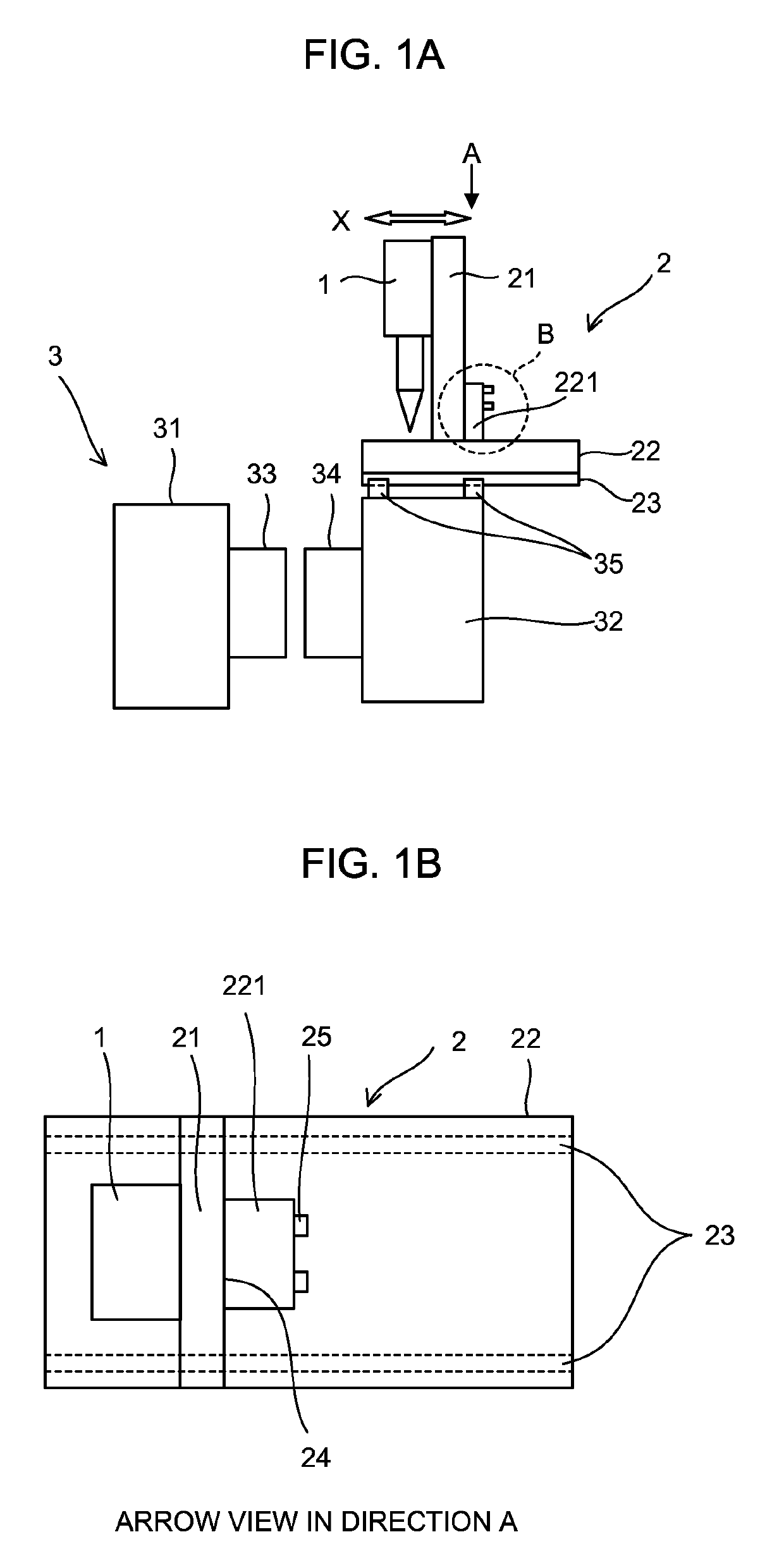
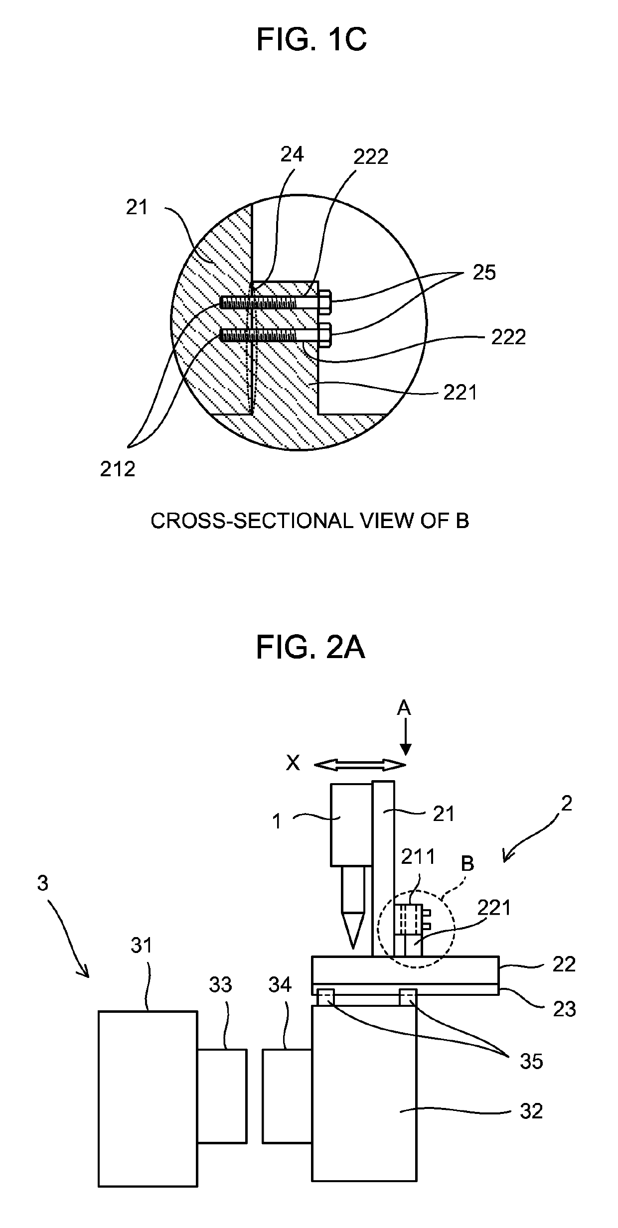
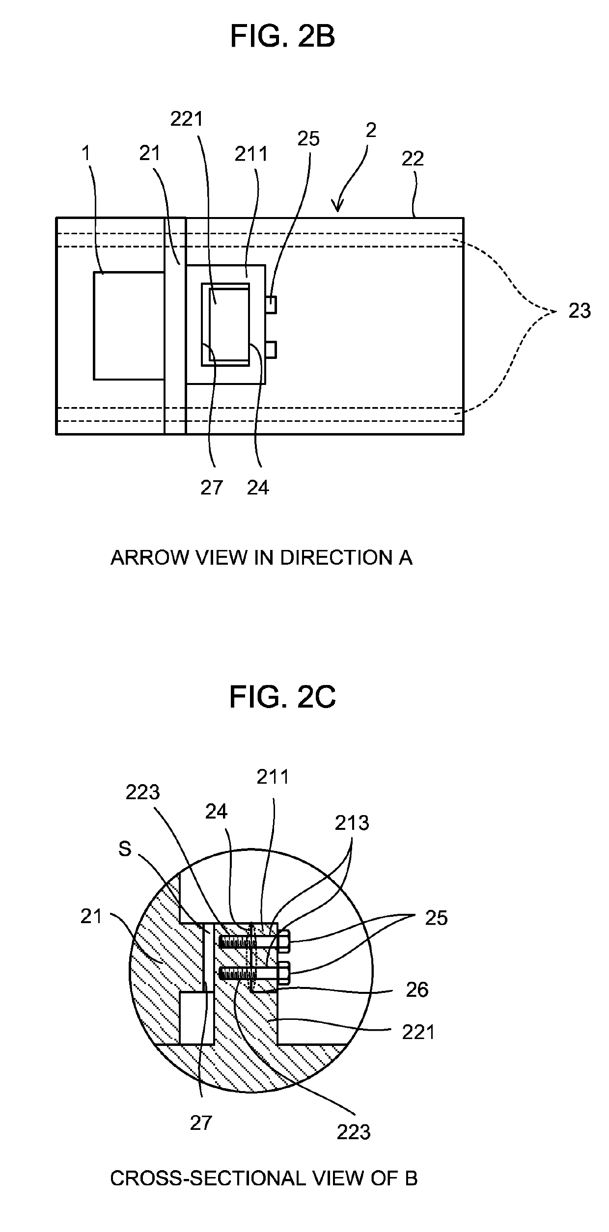
[0028]First, a description will be given of a first embodiment of an injection molding apparatus including a mounting stand of the invention using FIG. 1A, FIG. 1B, and FIG. 1C.

[0029]FIG. 1A is an overall view of the injection molding apparatus including amounting stand 2 according to the present embodiment.

[0030]An injection apparatus 1 is attached to the mounting stand 2. The mounting stand 2 is disposed above a mold clamping device 3. The injection molding apparatus closes and clamps molds 33 and 34 using the mold clamping device 3, injects a material into the molds 33 and 34 from the injection apparatus 1, and takes out a molded article from the molds 33 and 34.

[0031]An outline of a molding operation of the injection molding apparatus will be shown below.

[0032]The mold 33 is attached to a movable platen 31, the mold 34 is attached to a fixed platen 32, the movable platen 31 is moved toward the fixed platen 32, and the mold 33 and the mold 34 are closed to form an injection space...


PUM

PropertyMeasurementUnit
stabilityaaaaaaaaaa
shapeaaaaaaaaaa
dimensionsaaaaaaaaaa

Abstract

A mounting stand for an injection molding machine has a base member and an erecting member, to which an injection apparatus is attached, vertically arranged on the base member, and is movable with respect to a support supporting the base member. The mounting stand includes a base member protruding portion provided upward from the base member around a portion at which the base member comes into contact with the erecting member, and an anchored portion at which a side surface of the base member protruding portion is anchored to a side surface of the erecting member.

Description

RELATED APPLICATIONS[0001]The present application claim priority to Japanese Patent Application Number 2016-016543, filed Jan. 29, 2016, the disclosure of which is hereby incorporated by reference herein in its entirety.BACKGROUND OF THE INVENTION[0002]1. Field of the Invention[0003]The present invention relates to a mounting stand for an injection apparatus and an injection molding apparatus, and particularly relates to a mounting stand to which a vertical type injection apparatus is attached.[0004]2. Description of the Related Art[0005]In a mounting stand to which an injection apparatus of an injection molding machine is movably attached, the attached injection apparatus needs to be stably fixed. In addition, in the mounting stand, vibration is generated when the injection apparatus moves with respect to the mounting stand or when the injection apparatus is driven, and thus stability is required with respect thereto. In particular, in the case of a vertical type injection apparatu...

Claims


Application Information

Patent Timeline
Patent Type & Authority Patents(United States)
IPC IPC(8): B29C45/17F16M11/04B29C45/07F16M11/16B29C45/64B29C45/03B29C45/70
CPCB29C45/1742B29C45/03B29C45/07B29C45/17F16M11/041F16M11/043F16M11/16B29C45/64B29C45/70B29C45/1761
Inventor LI, ZHENXINGNISHIMURA, KOICHIYANO, SATOSHISUGAHARA, KEISUKE
Owner FANUC LTD
Why Eureka
Try Eureka