Earth working machine and method for wear-optimized operation of an earth working machine

a technology of earth working machine and wear-optimized operation, which is applied in the direction of electric programme control, instruments, roads, etc., can solve the problems of reducing replacement parts cost and prolonging maintenance intervals, and achieve the effect of further improving the working process of earth working machines

Active Publication Date: 2019-05-14
WIRTGEN GMBH
View PDF51 Cites 4 Cited by
  • Summary
  • Abstract
  • Description
  • Claims
  • Application Information

AI Technical Summary

Benefits of technology

[0010]The object is achieved by a method for wear-optimized operation of an earth working machine, in particular a road milling machine, a surface miner, or the like, at least one material property of the material to be removed being sensed in a processing device, and at least one machine parameter of a machine parameter set of the earth working machine being ascertained, as a function of at least the one material property, as a target machine parameter for establishing wear-optimized operation. The rate at which the earth working tools of the earth working machine wear depends substantially on two factors: on the one hand the material properties of the material to be removed, and on the other hand the existing machine parameters with which the earth working machine is operated. While the material properties are defined by the material to be worked, according to the present invention the machine parameters are set in such a way that the earth working machine is operated with the minimum possible wear or with a specified or permitted rate of wear on the earth working tools. The machine parameters respectively suitable for this depend on the existing material properties. Provision is therefore made that the material properties are sensed by the processing device and are considered in ascertaining the at least one target machine parameter. For purposes of the invention, “sensing” of the material properties means that they are, for example, inputted or are delivered to the processing device via corresponding signal lines, or that data from which the processing device determines the material properties are inputted into or delivered to said device. Various machine parameters that influence wear are advantageously grouped into a machine parameter set with which the earth working machine is operated. Different target values for one or more machine parameters of the machine parameter set are respectively provided depending on the existing material properties, which values result, in the context of the existing material properties, in a low or a specified rate of wear on the earth working tools. The invention thus makes possible wear-optimized operation of the earth working machine, with the result that maintenance costs for checking and replacing the working tools are kept low. Checking cycles for inspecting the wear state of the earth working tools can be lengthened. The earth working tools need to be changed less often, which results in extended maintenance intervals and lower replacement part costs. The wear can furthermore be influenced in such a way that maintenance or replacement of the earth working tools can occur at a favorable point in time, for example during a stoppage of the earth working machine for which provision is made in any case. Downtime costs can thereby be kept low.
[0030]The object of the invention relating to the earth working machine is achieved in that at least one material property is storable in the memory unit; that at least one characteristics diagram and / or at least one function is stored in the memory unit, the characteristics diagram and / or the function describing a correlation between a wear on the earth working tools and at least the one material property and at least one machine parameter; and that the calculation unit is designed to ascertain, based on the characteristics diagram and / or on the function and on the material property, at least one target machine parameter for which a minimum possible, or a specified, wear on the earth working tools exists. An earth working machine configured in this manner makes it possible to ascertain target machine parameters for which the earth working tools are subjected respectively to a minimum possible wear or to a specified wear. For this, one or more machine parameters are determined, with the aid of the characteristics diagram or the function, as a function of the existing material properties of the material to be removed, in such a way that the desired wear behavior exists.

Problems solved by technology

The earth working tools need to be changed less often, which results in extended maintenance intervals and lower replacement part costs.

Method used


Image

  • Earth working machine and method for wear-optimized operation of an earth working machine
  • Earth working machine and method for wear-optimized operation of an earth working machine
  • Earth working machine and method for wear-optimized operation of an earth working machine

Examples


Embodiment Construction

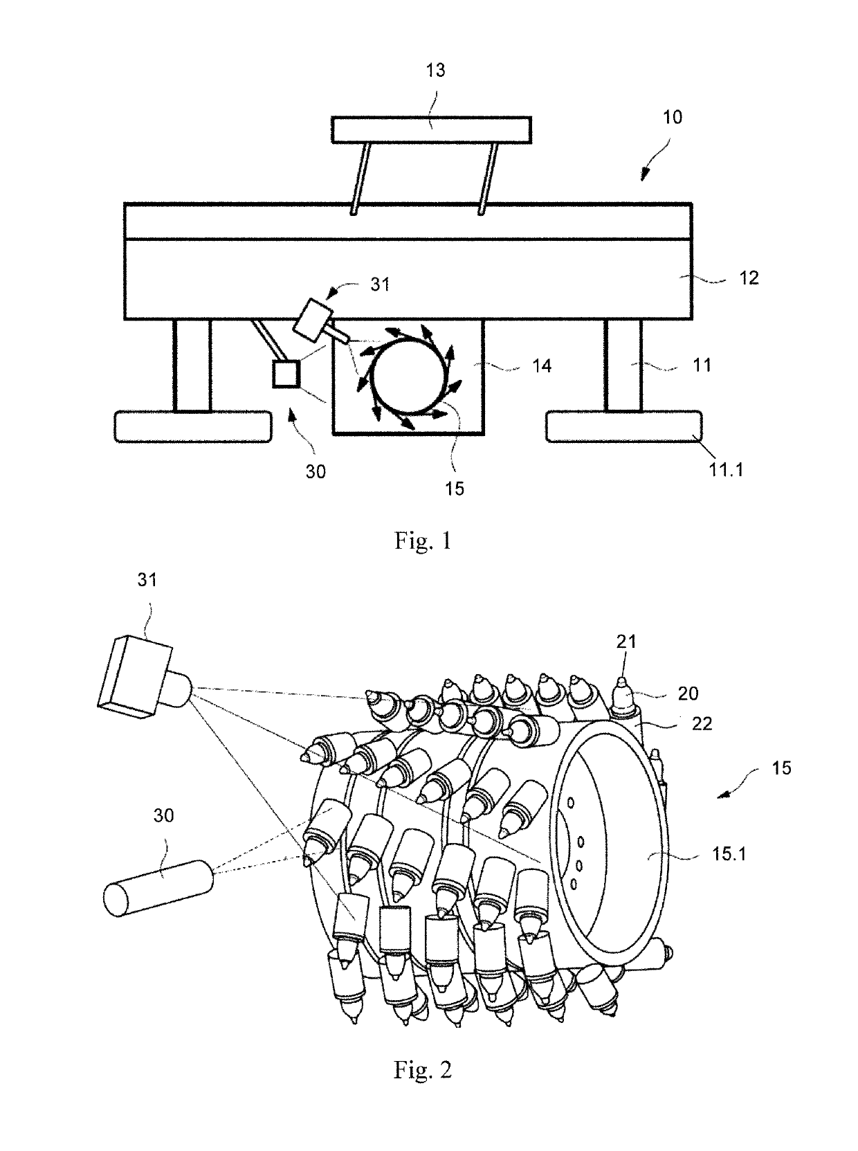
[0045]FIG. 1 symbolically depicts a milling machine 10, for example a surface miner, a road milling machine, or the like, in which a machine body 12 is carried by four drive units 11.1, for example crawler drive units, connected to machine body 12 vertically adjustably via lifting columns 11. Road milling machine 10 can be operated from a control station 13. A milling drum 15 is arranged in a milling drum box 14.

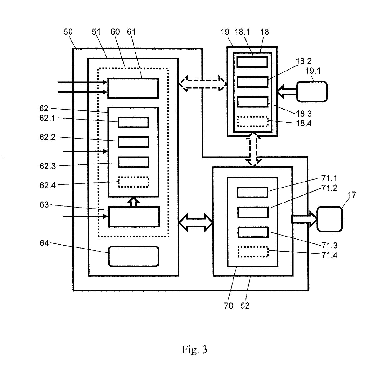
[0046]In the embodiment depicted, milling machine 10 offers the possibility of measuring in noncontact fashion the wear state of bits 20 and of bit holders 22 shown in FIG. 2. A light source 30 and a camera 31 are associated for that purpose with milling drum 15.

[0047]During use, machine body 12 is moved at a specified advance rate over the substrate to be worked, in which context bits 20 arranged on the rotating milling drum 15 remove the substrate. The vertical position and rotation speed of milling drum 15 can be adjusted.

[0048]FIG. 2 shows milling drum 15 in more detail....


PUM


Abstract

The invention relates to an earth working machine and to a method for wear-optimized operation of such an earth working machine. Provision is made in this context that machine parameters with which the earth working machine is operated are adapted, in consideration of material properties of the substrate to be worked, in such a way that favorable wear behavior exists for the earth working tools being used.

Description

BACKGROUND[0001]In the context of road reconstruction by milling and the removal of mineral deposits by means of surface miners (also by milling), the earth working tools that are used, and in particular the milling bits, are subject to a continuous wear process. Replacement is advisable once the tools reach a specific wear state, since otherwise the ongoing process loses efficiency.[0002]The wear state of the bits and bit holders can be assessed by visual inspection by the machine driver. The wear state of the bit holders is usually assessed by way of so-called wear markings. The wear state of the bits is assessed by way of the longitudinal wear and the rotational symmetry of the wear pattern.[0003]Inspecting the wear state of bits and holders is very time-intensive, and is unproductive since nothing can be produced during that time. The overall process is disrupted and the availability of the earth working machine is thus additionally decreased. It is therefore advantageous if the...

Claims


Application Information

Patent Timeline
Patent Type & Authority Patents(United States)
IPC IPC(8): E01C23/088G05D1/02E21C25/10E21C35/18
CPCE21C25/10G05D1/0219E21C35/18E01C23/088G05B19/04E21C47/00
Inventor BARIMANI, CYRUSHAHN, GUNTERWAGNER, STEFAN
Owner WIRTGEN GMBH
Why Eureka
Try Eureka