
Devices and methods for determining the position of a characterizing point of an eye and for tracking the direction of the gaze of a wearer of spectacles

a technology of eye and gaze direction, applied in the field of eye characterizing point and eye characterizing point and the direction of gaze of the wearer of spectacles, can solve the problems of wearer visual behavior, not allowing the gaze direction to be tracked under natural conditions, and the device cannot track the gaze direction

Active Publication Date: 2019-05-14
ESSILOR INT CIE GEN DOPTIQUE
View PDF15 Cites 1 Cited by
  • Summary
  • Abstract
  • Description
  • Claims
  • Application Information

AI Technical Summary

Benefits of technology

[0046]Tracking gaze directions during various tasks of the individual for example allows the zones of use of the ophthalmic lenses intended to equip the pair of spectacles of the individual, and in particular the far- and near-vision zones of the individual, to be determined with precision.
[0055]It is then possible to deduce therefrom the gaze directions of the wearer during various tasks of the individual thereby allowing the position and extent of the far- and near-vision zones of the individual on the corresponding ophthalmic lens intended for the wearer and for the frame chosen thereby to be deduced with precision.
[0062]Thus, the method according to the invention permits the gaze direction of the wearer to be determined under the usual visual behavior and posture conditions of the individual.
[0063]Determining the gaze directions of the individual during various tasks allows the position and extent of the far- and near-vision zones of the individual on the corresponding ophthalmic lens intended for the wearer and for the frame chosen thereby to be deduced with precision.

Problems solved by technology

014]However, these devices for tracking gaze direction have the drawback of not allowing this gaze direction to be tracked under natural, i.e. unconstrained, wearer visual behavior and posture conditions since the wearer must stand up or sit down in front of the measuring totem or hold the measuring tablet in his hands.

Method used


Image

  • Devices and methods for determining the position of a characterizing point of an eye and for tracking the direction of the gaze of a wearer of spectacles
  • Devices and methods for determining the position of a characterizing point of an eye and for tracking the direction of the gaze of a wearer of spectacles
  • Devices and methods for determining the position of a characterizing point of an eye and for tracking the direction of the gaze of a wearer of spectacles

Examples


first embodiment

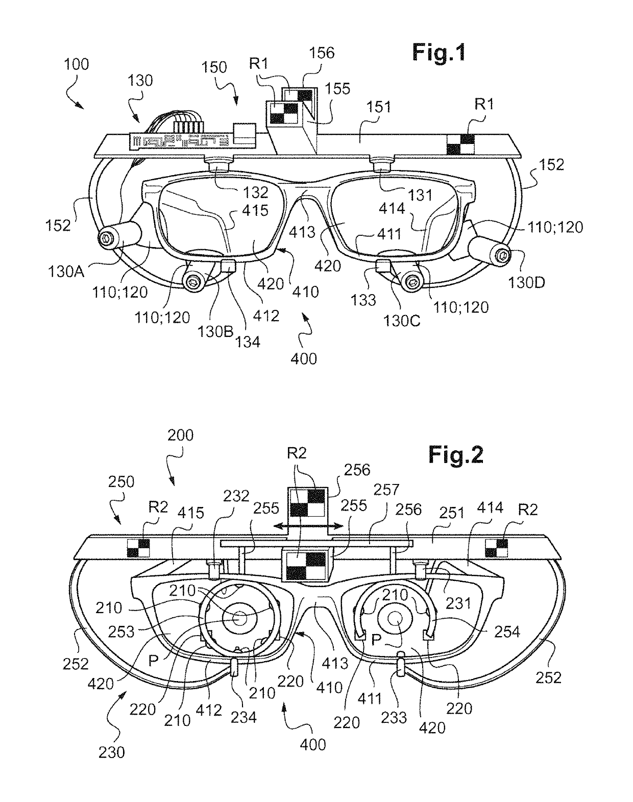
[0079]FIG. 1 is a schematic front view of a pair of spectacles equipped with the device for tracking gaze according to the invention,

second embodiment

[0080]FIG. 2 is a schematic front view of a pair of spectacles equipped with the device for tracking gaze according to the invention,

third embodiment

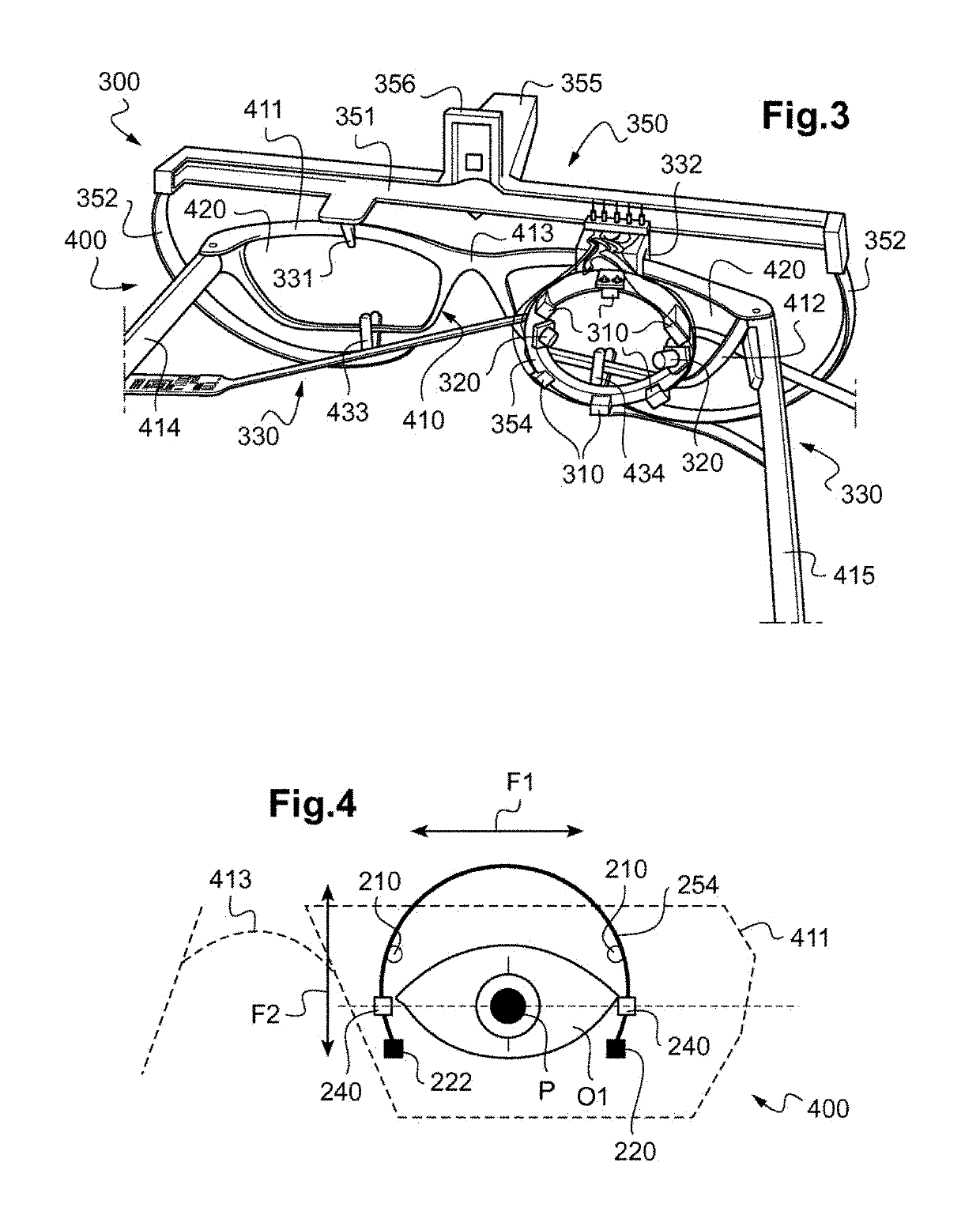
[0081]FIG. 3 is a schematic rear perspective view of a pair of spectacles equipped with the device for tracking gaze according to the invention,

[0082]FIG. 4 is a partial schematic view of the device for tracking gaze in FIG. 2,

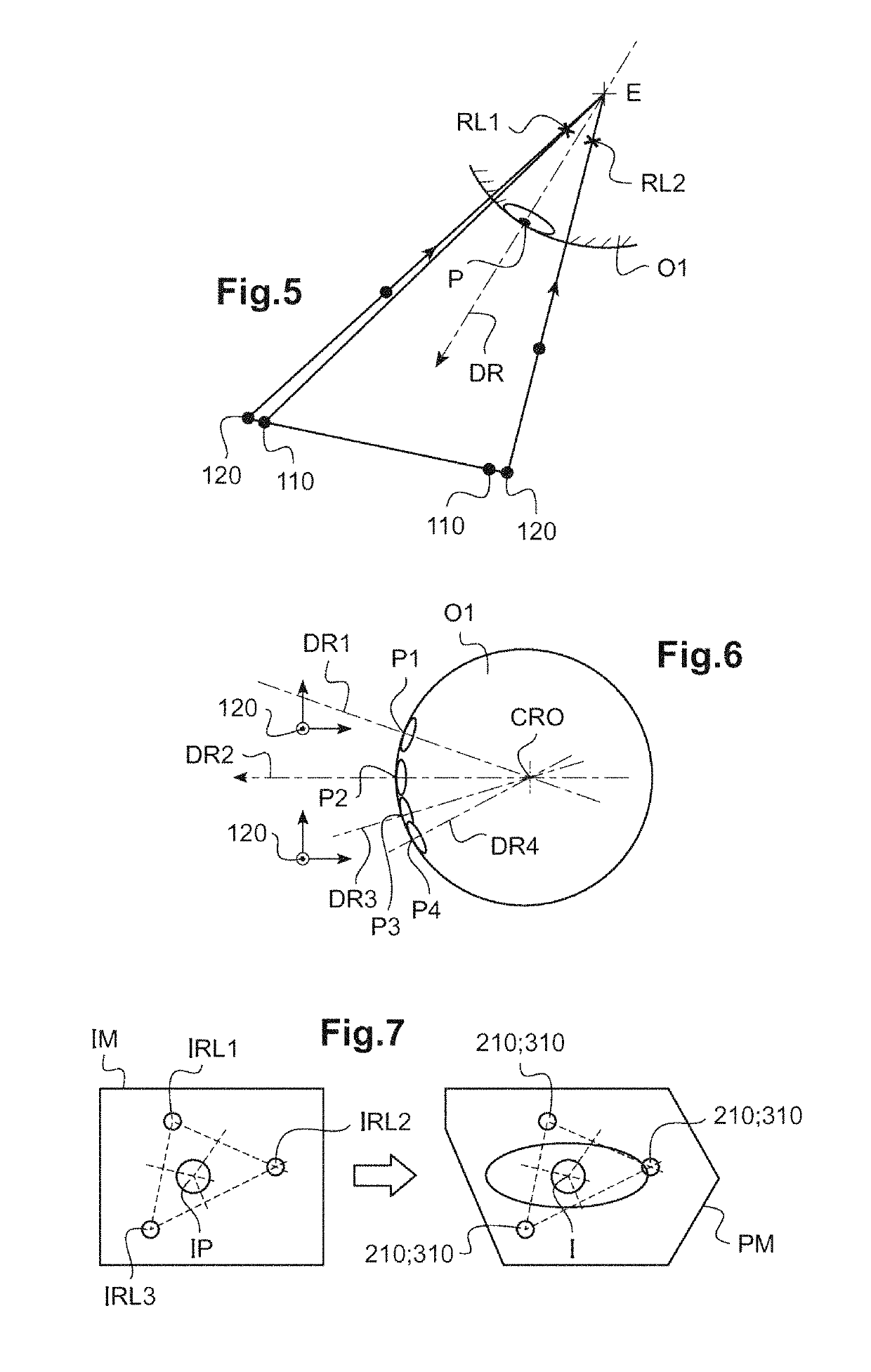
[0083]FIGS. 5 to 7 illustrate various implementations of the method for tracking gaze directions according to the invention.


PUM


Abstract

The invention relates to a device for determining the position of a characterizing point of an eye of a wearer provided with a spectacle frame (400), including: at least one image sensor apparatus (120); and positioning element for positioning the image sensor device relative to the spectacle frame (400), such that, when the spectacle frame is arranged in a useful position on the head of the wearer, the image sensor apparatus is capable of capturing an image of the eye of the wearer; and element for determining the position of a characterizing point of the eye from the at least one image of the eye of the wearer captured by the image sensor apparatus. The invention also relates to a method for determining the position of a characterizing point of an eye of a wearer, a device and a method for determining the direction of the gaze and a method for determining associated areas of wear of an ophthalmic lens.

Description

TECHNICAL FIELD OF THE INVENTION[0001]The present invention generally relates to the field of devices and methods for determining the position of a noteworthy point of an eye of an individual and to devices and methods for tracking the gaze direction of an individual.[0002]One particularly advantageous application thereof is to the implementation of a method for determining zones of use of ophthalmic lenses for a wearer of a vision frame.TECHNOLOGICAL BACKGROUND[0003]It is sought, in the context of the design of personalized ophthalmic vision-correcting lenses, to take into account individual geometrico-postural parameters of the wearer (referred to as personalized optical design parameters) and the frame he has chosen.[0004]The sought-after geometrico-postural parameters are related not only to the geometry of the head of the wearer and to that of the chosen spectacle frame, but also to the posture of the wearer and to his visual behavior.[0005]In order to determine these parameter...

Claims


Application Information

Patent Timeline
Patent Type & Authority Patents(United States)
IPC IPC(8): G02C13/00A61B3/113
CPCA61B3/113G02C13/005
Inventor FAYOLLE, ROMAINCHENE, SYLVAIN
Owner ESSILOR INT CIE GEN DOPTIQUE
Learn More