
Cable

Active Publication Date: 2019-05-14
TSUBAKIMOTO CHAIN CO
View PDF15 Cites 0 Cited by
  • Summary
  • Abstract
  • Description
  • Claims
  • Application Information

AI Technical Summary

Benefits of technology

The present invention provides a cable that is stable when its beginning and end are moved relative to each other and has a curved part in the middle. This structure protects the transmission member from the multi-joint support member and reduces the weight of the support member compared to using metal. The cable is stabilized while moving and has a curved part in the middle, which means it is more reliable and efficient.

Problems solved by technology

However, the path of the cable is unstable.

Method used


Image

  • Cable
  • Cable
  • Cable

Examples


modified example

[0055]The above embodiment may be modified as described below.

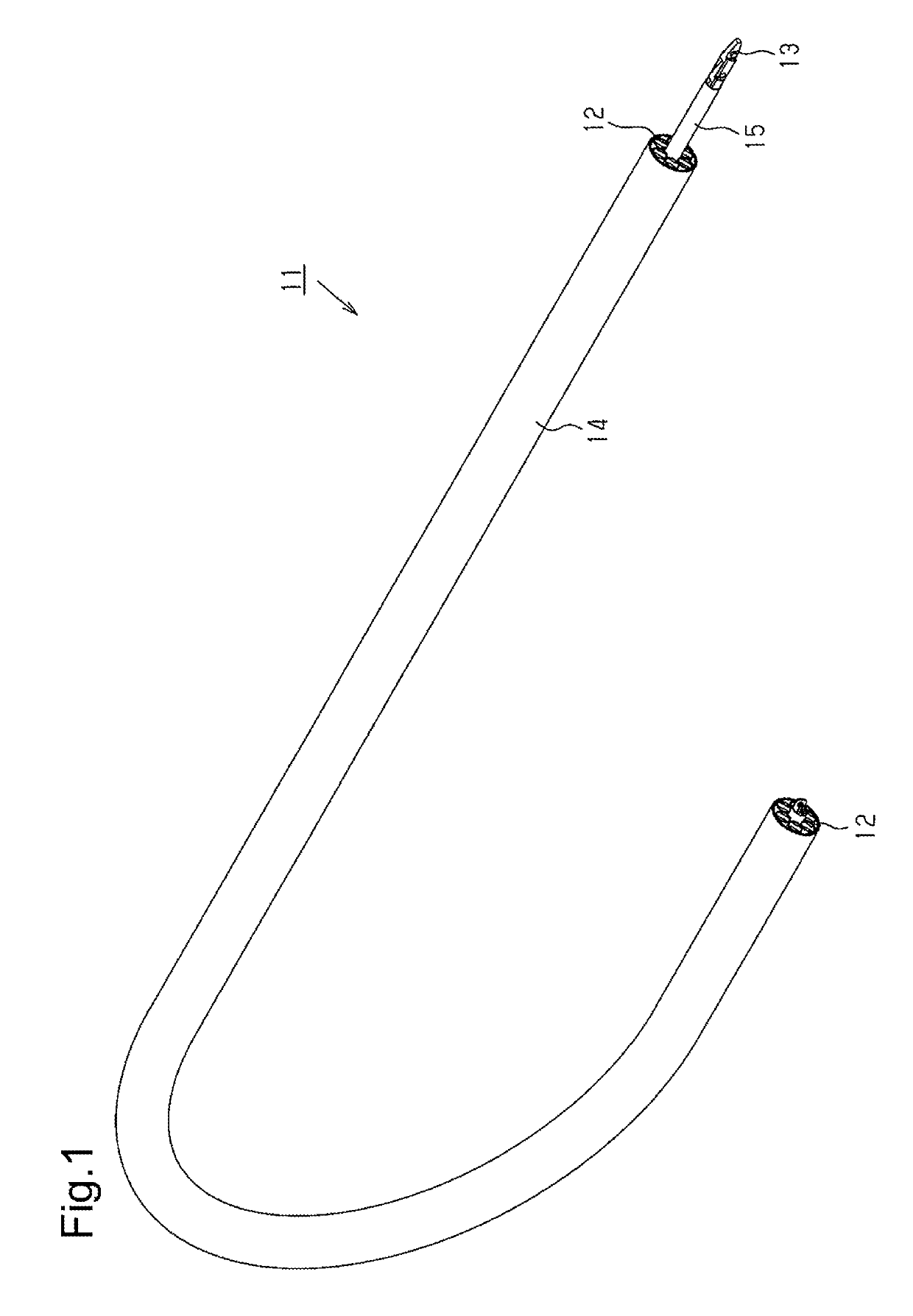
[0056]As shown in FIG. 8, in the cable 11, the cover member 15 may be omitted.

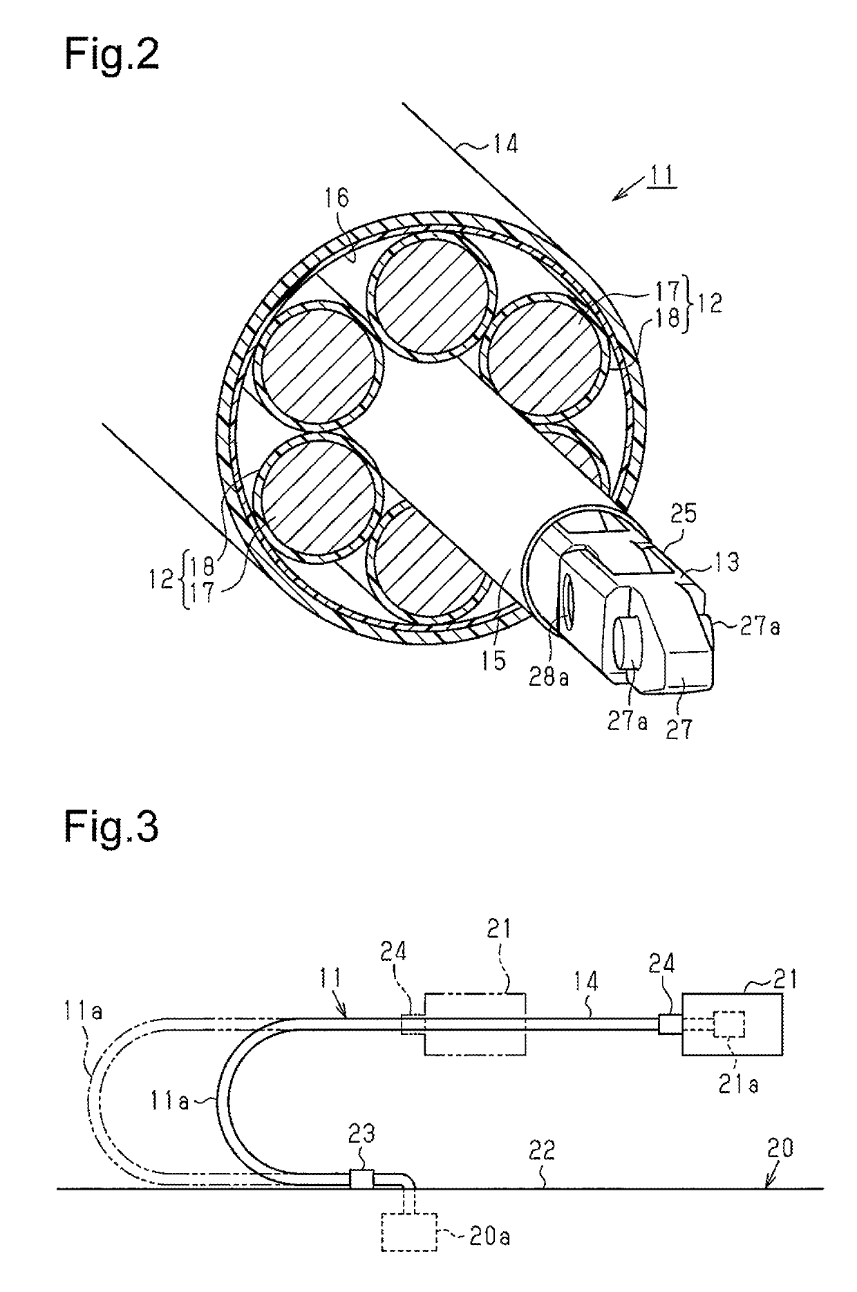
[0057]In the cable 11, the number of multi-joint support members 13 and the number of coated wires 12 covered by the sheath member 14 may be changed. For example, as shown in FIG. 9, in the cable 11, three of the six coated wires 12 may be changed to multi-joint support members 13, and the three multi-joint support members 13 and the remaining three coated wires 12 may be alternately arranged in a circumferential direction of the cable 11. In this case, the four multi-joint support members 13, that is, all of the multi-joint support members 13, are arranged so that they are bendable in the same direction. In the cable 11, the arrangement of a plurality of multi-joint support members 13 further increases the rigidity of the cable 11.

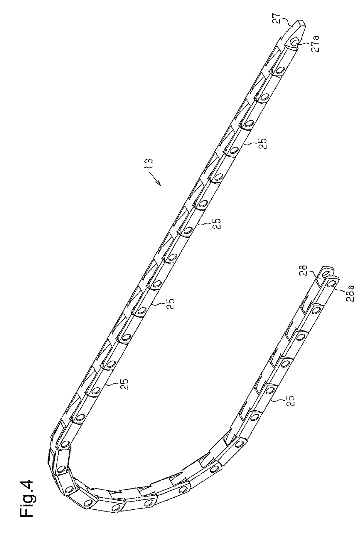
[0058]As shown in FIG. 10, the two side walls 281 of each link member 25 of the multi-joint support member 13 may b...


PUM


Abstract

A cable includes a flexible coated wire, a multi joint support member, and a flexible sheath member that covers the multi joint support member and the coated wire. The multi-joint support member is formed by pivotally coupling adjacent ones of a plurality of link members arranged in series. Turning of the multi joint support member in a first direction in a direction intersecting a serial direction is allowed until becoming equal to a predetermined radius of curvature and turning of the multi joint support member in a second direction, which is opposite to the first direction, is restricted.

Description

BACKGROUND OF THE INVENTION[0001]The present invention relates to a cable that supplies, for example, electric power.[0002]Such type of a cable known in the art includes a coated electric wire that has a conductor and a coating portion that coats the conductor, an insulative sheath portion that covers the coated electric wire, and a filler that fills the space between an inner side of the insulative sheath portion and an outer side of the coated electric wire (for example, patent document 1). Such a cable is flexible and configured to be freely bent.PRIOR ART DOCUMENTPatent Document[0003]Patent Document 1: Japanese Laid-Open Patent Publication No. 2012-146542SUMMARY OF THE INVENTION[0004]The above cable can be freely bent in any direction. Thus, when the cable is used to reciprocate a movable body in a horizontal direction with a first end fixed to a fixed portion and a second end fixed to the movable body that is located above the fixed portion, the cable moves while elastically de...

Claims


Application Information

Patent Timeline
IPC IPC(8): H01B11/04H01B7/22H02G3/04H01B7/04H01B7/02H02G11/00F16G13/16
CPCH01B7/04H01B7/02H01B7/223H02G11/00H02G3/0475H01B7/041F16G13/16H01B9/006
Inventor TETSUKA, TAKAYUKIKUNII, MASASHI
Owner TSUBAKIMOTO CHAIN CO
Features
  • Generate Ideas
  • Intellectual Property
  • Life Sciences
  • Materials
  • Tech Scout
  • Unparalleled Data Quality
  • Higher Quality Content
  • 60% Fewer Hallucinations
Learn More