Area illumination system and method

an illumination system and area technology, applied in lighting and heating apparatus, instruments, lighting support devices, etc., can solve problems such as difficult to accurately determine the aiming location in the field, installers may have difficulty in correctly aiming the luminaires, and not without problems

Active Publication Date: 2019-05-14
SIGNIFY HLDG BV
View PDF11 Cites 3 Cited by
  • Summary
  • Abstract
  • Description
  • Claims
  • Application Information

AI Technical Summary

Benefits of technology

[0010]The present invention seeks to provide an illumination system for generating a predefined illumination pattern on an area without having to rely on the correct implementation of an accurate light plan.
[0011]The present invention further seeks to provide a method of generating a predefined illumination pattern on an area without having to rely on the correct implementation of an accurate light plan.
[0014]In a preferred embodiment, the orientation adjustment mechanism is an electronically controllable orientation adjustment mechanism, and wherein the orientation adjustment signal is for controlling the electronically controllable orientation adjustment mechanism. This has the advantage that the luminaires may be automatically adjusted without installer intervention.
[0020]In an embodiment, the control unit is further adapted to adjust the intensity of the contribution to the illumination pattern generated by the selected luminaire to achieve the predefined illumination pattern. By adjusting both the orientation of the luminaires and the intensity of their respective contributions, the predefined illumination pattern can be more easily achieved.
[0021]Each luminaire may have a camera mounted on the luminaire, wherein a field of view of said camera is aligned with a direction in which the associated luminaire generates its contribution. This provides particularly reliable optical feedback to the control unit. Alternatively, each camera may be associated with more than one luminaire, e.g. placed such that it can capture the luminous distributions of multiple luminaires.
[0026]According to another aspect, there is provided a computer-implemented method for generating a predefined illumination pattern on an area with a plurality of luminaires each comprising an adjustable orientation mechanism and being arranged to generate a contribution to said illumination pattern on a part of said area, the method comprising repeating the steps of evaluating one of said images to determine a deviation from the predefined illumination pattern for the illuminated part of said area captured in said image; selecting a luminaire from said plurality of luminaires based on information in a light plan including positional information and aiming information for each luminaire; and generating an orientation adjustment signal for the selected luminaire based on the determined deviation until the predefined illumination pattern has been generated. In this manner, a predefined illumination pattern may be achieved in an iterative manner using optical feedback provided by cameras arranged to capture the contributions to the illumination pattern by the respective luminaires in order to correct imperfections in the light-plan based generation of a luminous pattern by the luminaires.

Problems solved by technology

This however is not without problems.
For example, the installer may have difficulty in correctly aiming the luminaires, for instance because of a lack of a clear reference on the area to aim at.
From the luminaire location, the installer has a clear overview of the field but it is very difficult to accurately determine the aiming location in the field.
However, the placement of the visual markers on the area is an elaborate task and the alignment itself based on the laser spot is prone to errors.
Moreover, such a procedure is less suitable for vertical areas, e.g. façades.
In addition, the installer may find that a particular luminaire cannot be aimed at the desired area location because of an obstacle in the light path of the luminaire that the light designer was unaware of when (remotely) deciding the mounting positions for the luminaire or because the intended mounting location of the luminaire is unavailable, in which case the installer usually mounts the luminaire in the nearest available location.
In this scenario, the provided light plan is imperfect such that the installer cannot achieve the predefined illumination pattern even when perfectly implementing the provided light plan.
These problems can lead to the resulting actual illumination pattern on the area deviating from the predefined illumination pattern, e.g. containing excessive inhomogeneities, such that some adjustment of the luminaire arrangement is required.
Although this can improve the aiming accuracy of the luminaire installation, it for instance does not assist the installer when encountering obstacles in the light path of the luminaires.

Method used


Image

  • Area illumination system and method
  • Area illumination system and method
  • Area illumination system and method

Examples


Embodiment Construction

[0033]It should be understood that the Figures are merely schematic and are not drawn to scale. It should also be understood that the same reference numerals are used throughout the Figures to indicate the same or similar parts.

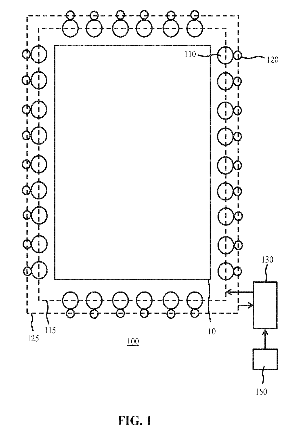
[0034]Embodiments of the present invention relate to an illumination system for illuminating an area of given size, i.e. an area having known dimensions. Such dimensions for instance may be provided as input parameters or in any other suitable form to the system. The illumination system is typically to be arranged to generate a predefined illumination pattern onto the area of given size. In at least some embodiments, the predefined illumination pattern is a homogeneous or uniform illumination pattern. In at least some other embodiment, the predefined illumination pattern is a non-homogeneous or non-uniform illumination pattern. In the context of the present application, a homogeneous or uniform illumination pattern is an illumination pattern in which across t...


PUM


Abstract

Disclosed is an illumination system (100) and method (600) for generating a predefined illumination pattern on an area (10). The system comprises a plurality of luminaires (110), each luminaire having an orientation adjustment mechanism and being arranged to generate a contribution (210, 210′) to said illumination pattern on a part of said area; a plurality of cameras (120), each camera associated with one of said luminaires for capturing an image of an illuminated part of said area including the contribution generated by said associated luminaire; and a control unit (130) adapted to facilitate the generation of the predefined illumination pattern by evaluating one of said images to determine a deviation from the predefined illumination pattern for the illuminated part of said area captured in said image; selecting a luminaire from said plurality of luminaires from information contained in a light plan and generating an orientation adjustment signal for the selected luminaire based on the determined deviation.

Description

CROSS-REFERENCE TO PRIOR APPLICATIONS[0001]This application is the U.S. National Phase application under 35 U.S.C. § 371 of International Application No. PCT / EP2016 / 058744, filed on Apr. 20, 2016 which claims the benefit of European Patent Application No. 15165467.0, filed on Apr. 28, 2015. These applications are hereby incorporated by reference herein.FIELD OF THE INVENTION[0002]The present invention relates to an illumination system for generating a predefined illumination pattern on an area of a given size.[0003]The present invention further relates to a method for generating a predefined illumination pattern on an area of a given size.BACKGROUND OF THE INVENTION[0004]Many high-end lighting applications require a plurality of luminaires aimed at an area of given size to generate a predefined illumination pattern on the area. Examples of such applications include arena lighting systems for illuminating sports arenas, e.g. field, pitch or stadium lighting, façade lighting, shop flo...

Claims


Application Information

Patent Timeline
Patent Type & Authority Patents(United States)
IPC IPC(8): F21V21/14G06F17/50H05B37/02
CPCH05B37/029G06F17/5004F21V21/14H05B47/155G06F30/13
Inventor RAJAGOPALAN, RUBENBROERS, HARRY
Owner SIGNIFY HLDG BV
Why Eureka
Try Eureka