Umbrella rib connector assemblies and methods

a technology of connectors and ribs, applied in the direction of walking sticks, etc., can solve the problems of inability to replace broken ribs, no practical way to replace umbrella hubs, laborious manufacturing processes, etc., and achieve the effect of reducing replacement labor and cost, and protecting the structural integrity of umbrella hubs

Active Publication Date: 2019-05-21
MA ZHUN AN
View PDF190 Cites 8 Cited by
  • Summary
  • Abstract
  • Description
  • Claims
  • Application Information

AI Technical Summary

Benefits of technology

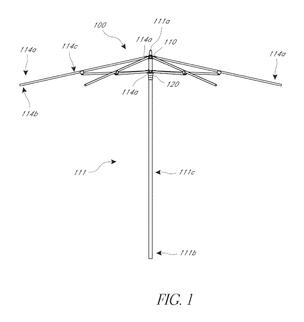
[0006]An aspect of at least one embodiment disclosed herein is the realization that prior art umbrella hubs or hub assemblies provide no convenient means for removing or replacing broken ribs. For example, the entire assembly must be entirely or partially disassembled and reassembled or the umbrella hub may be structurally damaged to remove a broken rib. In a one-piece hub there may be no practical way to replace a broken rib. Therefore, embodiments disclosed herein seek to remedy this deficiency by providing a hub assembly that can enable broken ribs to be removed and replaced with new ribs. Accordingly, it would also be beneficial to provide structures in an umbrella hub that enable broken ribs to be removed and replaced with new ribs to reduce replacement labor and cost and to protect structural integrity of the umbrella hub.
[0007]Another aspect of at least one embodiment disclosed herein is the realization that the structures of umbrella rib ends that are coupled with the umbrella hub can be greatly simplified. For example, prior art umbrella rib ends use individual pins that are each pivotably coupled within the umbrella hubs. These individual pins also provide the securement mechanism to connect the umbrella ribs to the umbrella hub. This tedious manufacturing process can be costly and frustrating. Accordingly, it would also be beneficial to provide structures in an umbrella hub and rib ends that enable the umbrella ribs to be securely coupled with the umbrella hubs but that do not require or lessen the reliance on individual pins in such coupling.
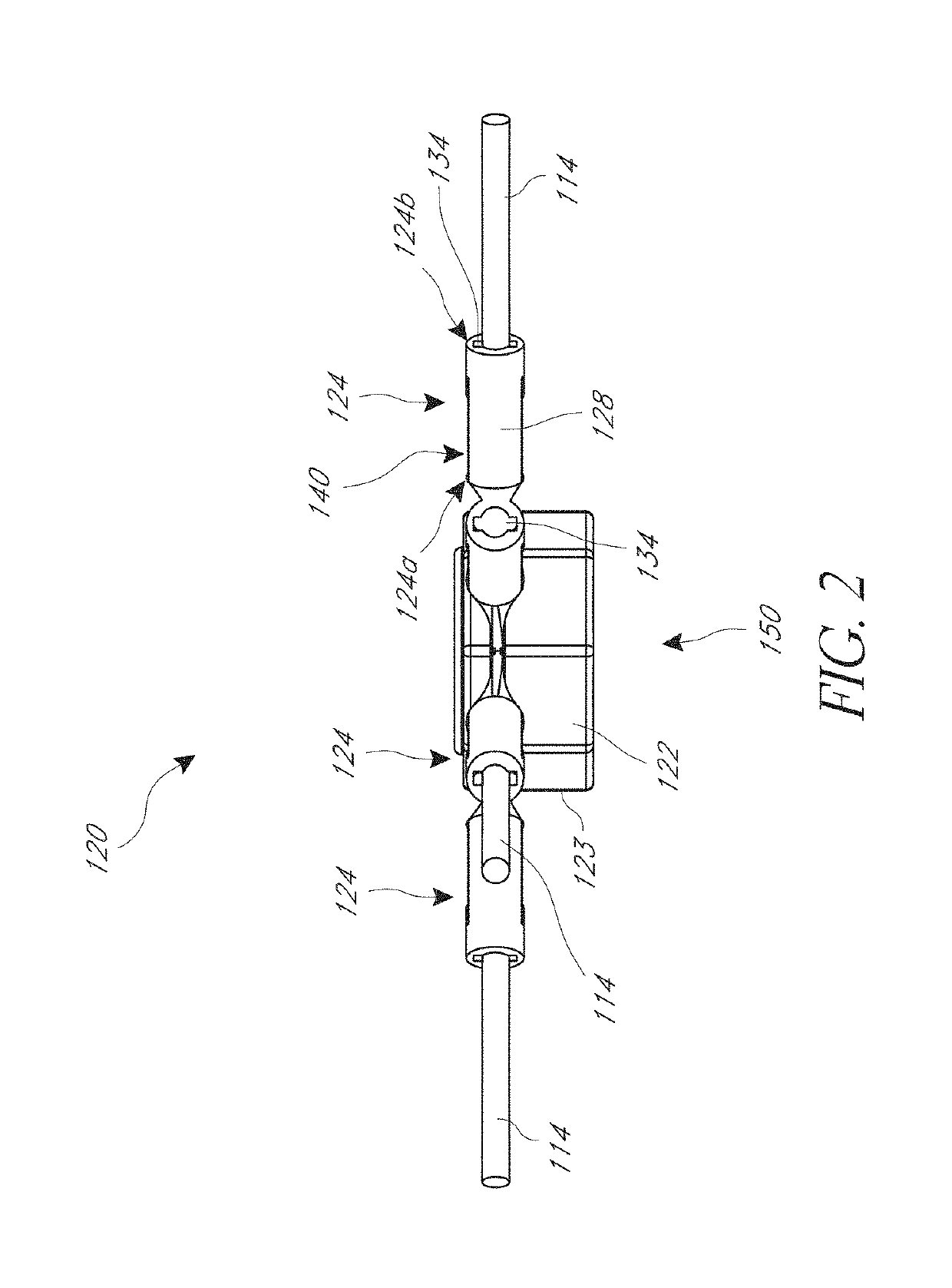
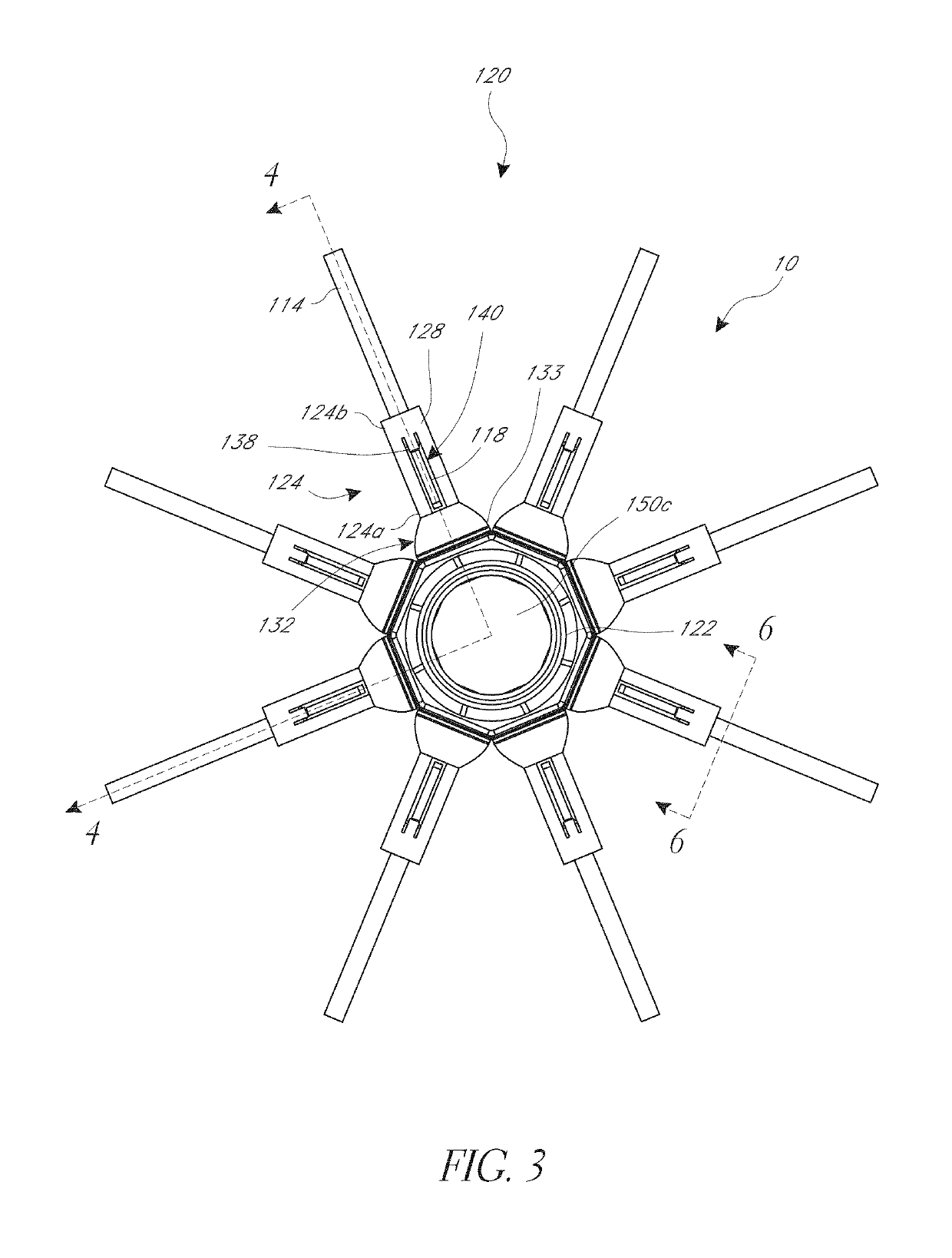
[0027]In another aspect, an umbrella assembly includes an elongate pole and an umbrella hub coupled with the elongate pole. The umbrella hub includes a cylindrical portion and a plurality of sockets. A socket of the plurality of sockets has a fixed end coupled with, e.g., integrally formed with, the cylindrical portion. A free end of the socket extends away from the cylindrical portion. A space within the socket can be accessible through an opening on the free end of the socket. The space includes a narrow region and a widened region. The narrow region can be located between the free end and the widened region. The umbrella assembly also includes an umbrella rib comprising an inner end, an outer end, and an elongate body extending along a longitudinal axis of the umbrella rib and disposed between the inner end and the outer end. The inner end of the umbrella ribs has a widened segment that can be wider in a direction transverse to the longitudinal axis of the umbrella rib than an adjacent segment. The adjacent segment can be disposed between the widened segment and the second end of the umbrella rib. The inner end can be configured to be received within the space through the opening and advanced through the narrow region to the widened region. A catch surface of the socket prevents the widened segment from being removed from the widened region back through the narrow region.
[0028]In another aspect, a method of assembling an umbrella rib includes inserting an inner end of an umbrella rib into a concave space through an opening at a free end of a socket. The socket can be coupled with, e.g., integrally formed with, a central hub. The method includes advancing the inner end through a narrow region of the concave space and elastically deforming or otherwise at least temporarily displacing a catch surface of the socket. The catch surface can be located between the narrow space and a widened region of the concave space. The method can include advancing the inner end out of the narrow region and into the widened region and blocking the return of the inner end of the umbrella rib back through the narrow region of the socket by the catch surface. The catch surface can at least partially return to an original position after having been elastically deformed and after the inner end can be advanced out of the narrow region.

Problems solved by technology

For example, the entire assembly must be entirely or partially disassembled and reassembled or the umbrella hub may be structurally damaged to remove a broken rib.
In a one-piece hub there may be no practical way to replace a broken rib.
This tedious manufacturing process can be costly and frustrating.

Method used


Image

  • Umbrella rib connector assemblies and methods
  • Umbrella rib connector assemblies and methods
  • Umbrella rib connector assemblies and methods

Examples


Embodiment Construction

[0043]While the present description sets forth specific details of various embodiments, it will be appreciated that the description is illustrative only and should not be construed in any way as limiting. Furthermore, various applications of such embodiments and modifications thereto, which may occur to those who are skilled in the art, are also encompassed by the general concepts described herein. Each and every feature described herein, and each and every combination of two or more of such features, is included within the scope of the present invention provided that the features included in such a combination are not mutually inconsistent.

[0044]Some embodiments have been described in connection with the accompanying drawings. However, it should be understood that the figures are not drawn to scale. Distances, angles, etc. are merely illustrative and do not necessarily bear an exact relationship to actual dimensions and layout of the devices illustrated. Components can be added, re...


PUM


Abstract

In one aspect of the present disclosure, an umbrella hub assembly comprises an a cylindrical portion and a socket coupled to the cylindrical portion. The socket can have a fixed end, a free end, and a cylindrical wall defining a concave space extending from the free end toward the fixed end. The socket can have an access aperture disposed through the cylindrical wall. The assembly can further include an umbrella rib comprising a first end, a second end, and an elongate body extending along a longitudinal axis. The first end can be configured to be received in the concave space through the free end such that the socket engages the umbrella rib and such that the first end is accessible through the access aperture.

Description

INCORPORATION BY REFERENCE TO ANY PRIORITY APPLICATIONS[0001]Any and all applications for which a foreign or domestic priority claim is identified in the Application Data Sheet as filed with the present application are hereby incorporated by reference under 37 C.F.R. § 1.57.BACKGROUND OF THE INVENTIONField of the Invention[0002]This application relates to apparatuses and methods that facilitate efficient assembly of ribs and hubs of umbrellas and other structures with a plurality of elongate structural members that extend from a central hub member.Description of the Related Art[0003]Larger umbrellas, such as market umbrellas, generally include a frame that is used to support and distribute the weight of an upper portion of the umbrella as well as to enable the umbrella to be opened and closed as desired by the user. The frame can take various forms, but often includes one or more hubs connected with a plurality of structural members. The structural members can move relative to the h...

Claims


Application Information

Patent Timeline
Patent Type & Authority Patents(United States)
IPC IPC(8): A45B25/02A45B25/10A45B25/08
CPCA45B25/02A45B25/10A45B25/08
Inventor MA, ZHUN-AN
Owner MA ZHUN AN
Why Eureka
Try Eureka