Vehicle-mounted millimeter-wave communication device and communication method

Active Publication Date: 2019-05-21
TOYOTA JIDOSHA KK
View PDF15 Cites 1 Cited by
  • Summary
  • Abstract
  • Description
  • Claims
  • Application Information

AI Technical Summary

Benefits of technology

[0023]According to the present invention, it is possible to impl

Problems solved by technology

In conventional arts, communication with a fixed specific communication partner is considered, or the transmission directi

Method used


Image

  • Vehicle-mounted millimeter-wave communication device and communication method
  • Vehicle-mounted millimeter-wave communication device and communication method
  • Vehicle-mounted millimeter-wave communication device and communication method

Examples


first embodiment

[0034]The present embodiment relates to a vehicle-mounted millimeter-wave communication device that performs communication by using millimeter waves. In the present specification, the “millimeter waves” mean radio waves in a band from 24 GHz to 86 GHz. The millimeter wave has high straightness, and hence it is necessary to appropriately control a communication direction. In particular, a positional relationship with a communication partner frequently changes in a vehicle environment. The present embodiment uses a communication device and a communication method suitable particularly for such a vehicle environment.

[0035]Configuration

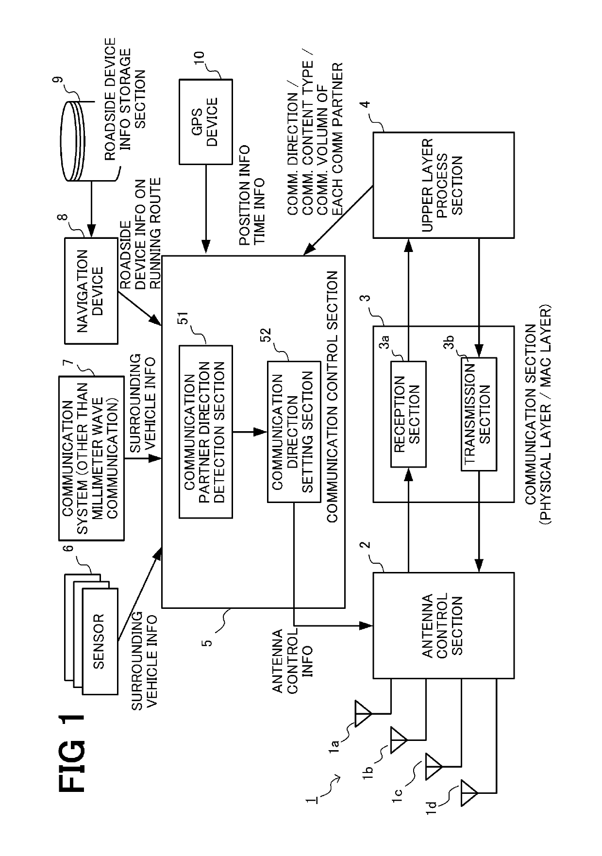
[0036]FIG. 1 is a view showing the configuration of the vehicle-mounted millimeter-wave communication device of the present embodiment. As shown in FIG. 1, the vehicle-mounted millimeter-wave communication device according to the present embodiment includes an antenna unit 1, an antenna control section 2, a communication section 3, an upper layer process s...

operation example

[0062]The communication time allocation in each of Steps S103 and S104 will be described in detail based on specific operation examples shown in FIGS. 5 to 7.

[0063]FIG. 5 is a view for explaining the case where the communication times that are equal to each other are allocated to all communication directions (the procedure in Step S104). Herein, a description will be made by using 10 milliseconds as one unit time (communication cycle). In the case where the communication times that are equal to each other are allocated to all directions, 10 milliseconds serving as the unit time is quartered, and 2.5 milliseconds is allocated to each of forward, backward, left, and right directions as the communication time. By using this basic slot repeatedly, it is possible to obtain communication opportunities equally with communication partners in all directions.

[0064]FIGS. 6A to 6D are views for explaining the case where the long communication time is allocated to the communication direction of ...

second embodiment

[0072]FIG. 8 is a view showing the configuration of a vehicle-mounted millimeter-wave communication device according to a second embodiment. The same components as those in the first embodiment are designated by the same reference numerals, and the repeated description thereof will be omitted.

[0073]The present embodiment is different from the first embodiment in that a communication content acquisition section 53 is provided in the communication control section 5. The communication content acquisition section 53 is the functional section that acquires details of the communication of the vehicle-mounted millimeter-wave communication device with the communication partner.

[0074]An example of the communication content acquired by the communication content acquisition section 53 is information indicative of the kind of information transmitted to or received from the communication partner using the millimeter wave communication, i.e., information indicative of the type of the communicatio...


PUM


Abstract

A vehicle-mounted millimeter-wave communication device for performing communication while temporally changing a communication direction by using an antenna unit capable of changing directivity includes: a detection unit configured to detect a direction of a communication partner present around a host vehicle; and a communication control unit configured to perform control such that communication is performed, in which a longer communication time is set for the direction of the communication partner than another direction. The communication control unit preferably performs control that sets a long communication time for the direction of the communication partner in the case where the type of the content of communication with the communication partner is related to control of a vehicle, and in the case where the volume of the communication with the communication partner is not less than a threshold value.

Description

BACKGROUND OF THE INVENTIONField of the Invention[0001]The present invention relates to millimeter wave communication, and more particularly relates to communication control that enables efficient communication in roadside-to-vehicle and vehicle-to-vehicle communication.Description of the Related Art[0002]The use of millimeter waves (a band from 24 GHz to 86 GHz) is proposed to implement high-capacity communication in the next generation mobile communication system (5G). The millimeter wave has high straightness, and hence it is necessary to appropriately adjust a communication direction (directivity) to perform communication.[0003]Japanese Patent Application Publication No. 2004-214864 (PTL1) describes a technique related to a communication antenna for a wireless LAN in a 2.4 GHz or 5.8 GHz band, and discloses that communication quality is maintained by changing the directivity of the antenna depending on the situation. Specifically, PTL1 discloses that communication with a communi...

Claims


Application Information

Patent Timeline
IPC IPC(8): G08G1/00G05D1/00H04B7/005H01Q1/32H01Q3/24H04W4/40G05D1/02H04W4/70
CPCG05D1/0257G05D1/0055H01Q1/3275H04W4/70H01Q3/24H04B7/005H04W4/40H01Q1/3283H04W4/38H01Q1/38H01Q1/50H01Q3/04H01Q3/247H04B7/0617H04B7/086H04W72/046
Inventor SAI, SEII
Owner TOYOTA JIDOSHA KK
Why Eureka
Try Eureka