
Ammonia generation apparatus and ammonia generation control apparatus

a technology of ammonia generation control and ammonia generation apparatus, which is applied in mechanical equipment, machines/engines, separation processes, etc., can solve the problem that urea water cannot be hydrolyzed

Inactive Publication Date: 2019-05-28
NGK SPARK PLUG CO LTD
View PDF27 Cites 1 Cited by
  • Summary
  • Abstract
  • Description
  • Claims
  • Application Information

AI Technical Summary

Benefits of technology

[0008]The ammonia generation apparatus according to the first mode can cause the selective catalytic reduction unit to function from a lower temperature range, independently of the temperature of exhaust gas, to thereby purify NOx even in a low exhaust gas temperature range.
[0013]The ammonia generation control apparatus according to the second mode can cause the selective catalytic reduction unit to function from a lower temperature range, independently of the temperature of exhaust gas, to thereby purify NOx even in a low exhaust gas temperature range.
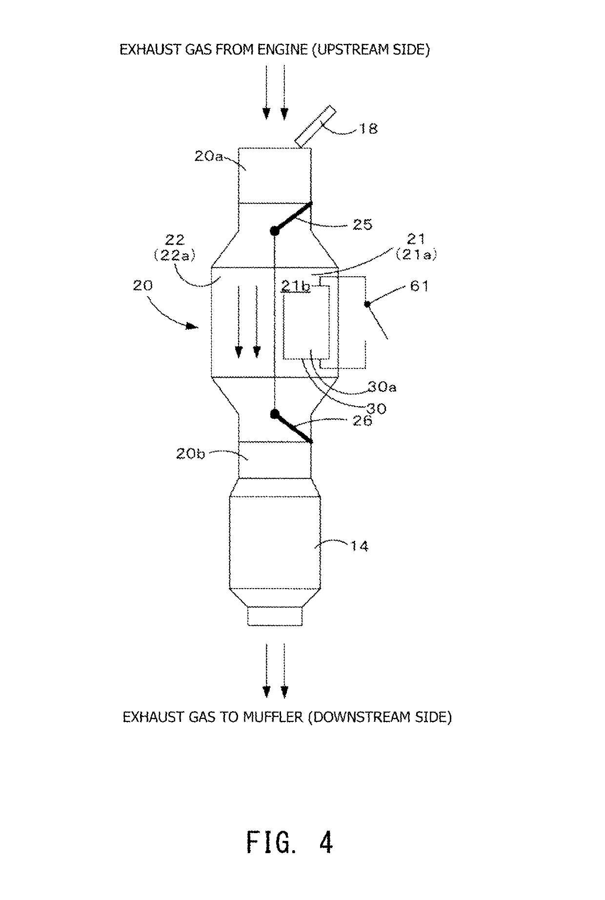
[0017]The ammonia generation control apparatus according to the second mode may be configured such that the control section further controls the supply of urea water by the urea water supply section and the operation of the heating unit; and, in the first operation state, the control section switches the flow passage of the exhaust gas to the first flow passage and causes the urea water supply section to supply urea water to the first flow passage, and, after completion of the supply of urea water to the first flow passage, the control section switches the flow passage of the exhaust gas to the second flow passage and operates the heating unit. In this case, it is possible to hydrolyze the supplied urea water using the heater unit without exposure to the flow of the exhaust gas.

Problems solved by technology

A temperature of about 200° C. is needed for hydrolysis of urea water, and when exhaust gas is used as a heat source or when a heat source for hydrolyzing urea water is disposed within an exhaust passage, there is a problem in that when the temperature of exhaust gas is low, the urea water cannot be hydrolyzed.

Method used


Image

  • Ammonia generation apparatus and ammonia generation control apparatus
  • Ammonia generation apparatus and ammonia generation control apparatus
  • Ammonia generation apparatus and ammonia generation control apparatus

Examples


first embodiment

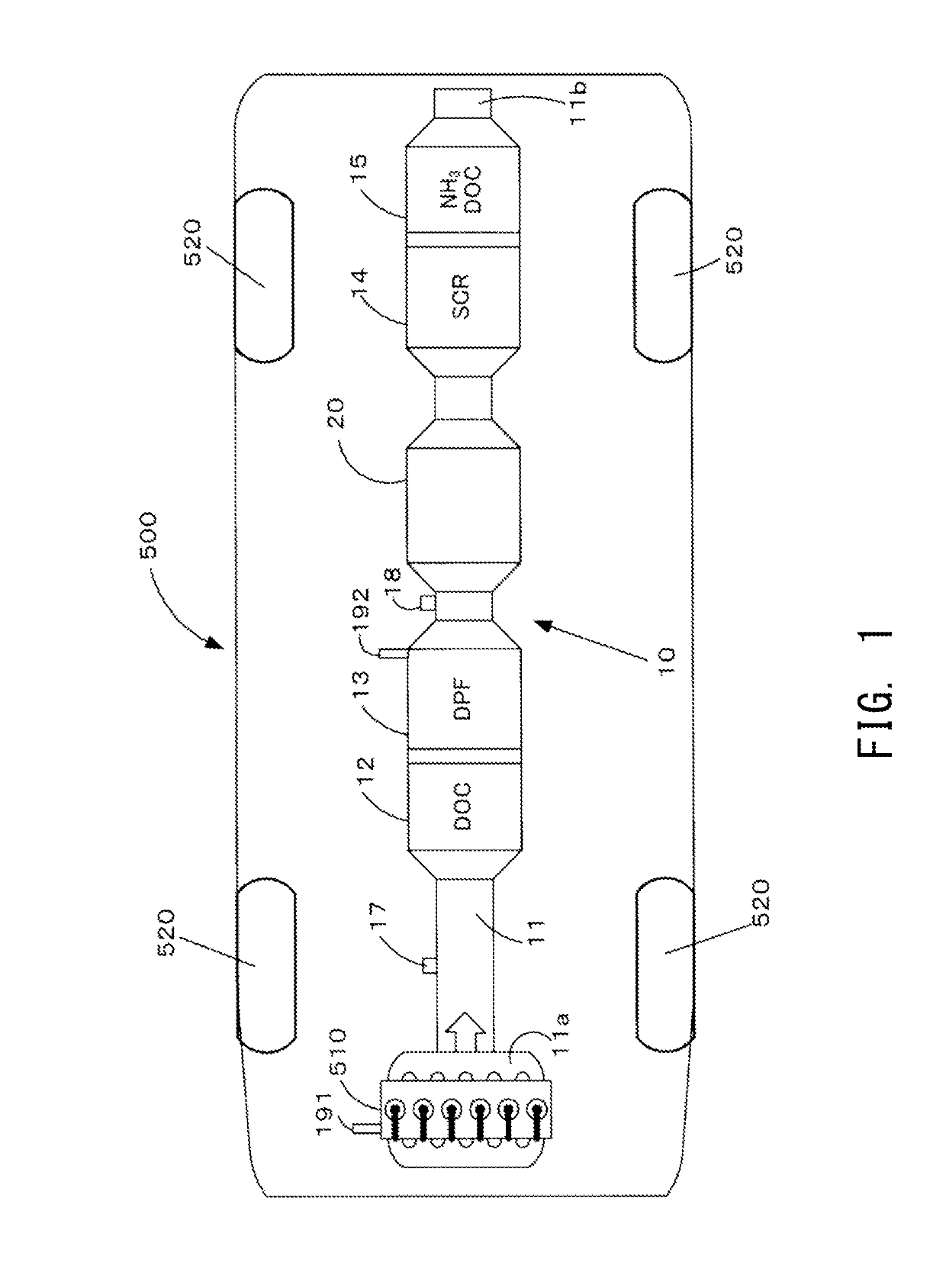
[0036]A vehicle 500 includes a diesel engine (hereafter referred to as the “engine”) 510, four wheels 520, and an exhaust gas purification system 10. An ammonia generation apparatus 20 according to the present embodiment is provided in the exhaust gas purification system 10. The engine 510 uses light oil as fuel and outputs drive force by means of explosive combustion of the fuel. Also, as a result of the explosive combustion, the engine 510 discharges exhaust gas containing NOx (nitrogen oxides) and PM (particulate matter) to the atmosphere through the exhaust gas purification system 10 provided in the exhaust system of the vehicle 500. A first temperature sensor 191 for detecting the temperature of coolant for cooling the engine 510 is provided on the engine 510. Notably, the configuration of the vehicle shown in FIG. 1 and used in the first embodiment can be used similarly in other embodiments.

[0037]The exhaust gas purification system 10 includes various types of exhaust gas puri...

second embodiment

[0082]An ammonia generation apparatus 20 according to a second embodiment will be described with reference to FIGS. 11 through 13. FIG. 11 is an explanatory view showing an operating state of the ammonia generation apparatus according to the second embodiment at the time of warming up. FIG. 12 is an explanatory view showing an operating state of the ammonia generation apparatus according to the second embodiment at the time of warming up. FIG. 13 is a flowchart showing a processing routine for controlling the operation of the ammonia generation apparatus in the second embodiment. The present processing routine is repeatedly executed by the control unit 60 at predetermined timings and time intervals. Notably, although the procedure of generating ammonia in the ammonia generation apparatus 20 according to the second embodiment differs from that in the ammonia generation apparatus 20 of the first embodiment, the components of the ammonia generation apparatus 20 according to the second ...


PUM

PropertyMeasurementUnit
temperatureaaaaaaaaaa

Abstract

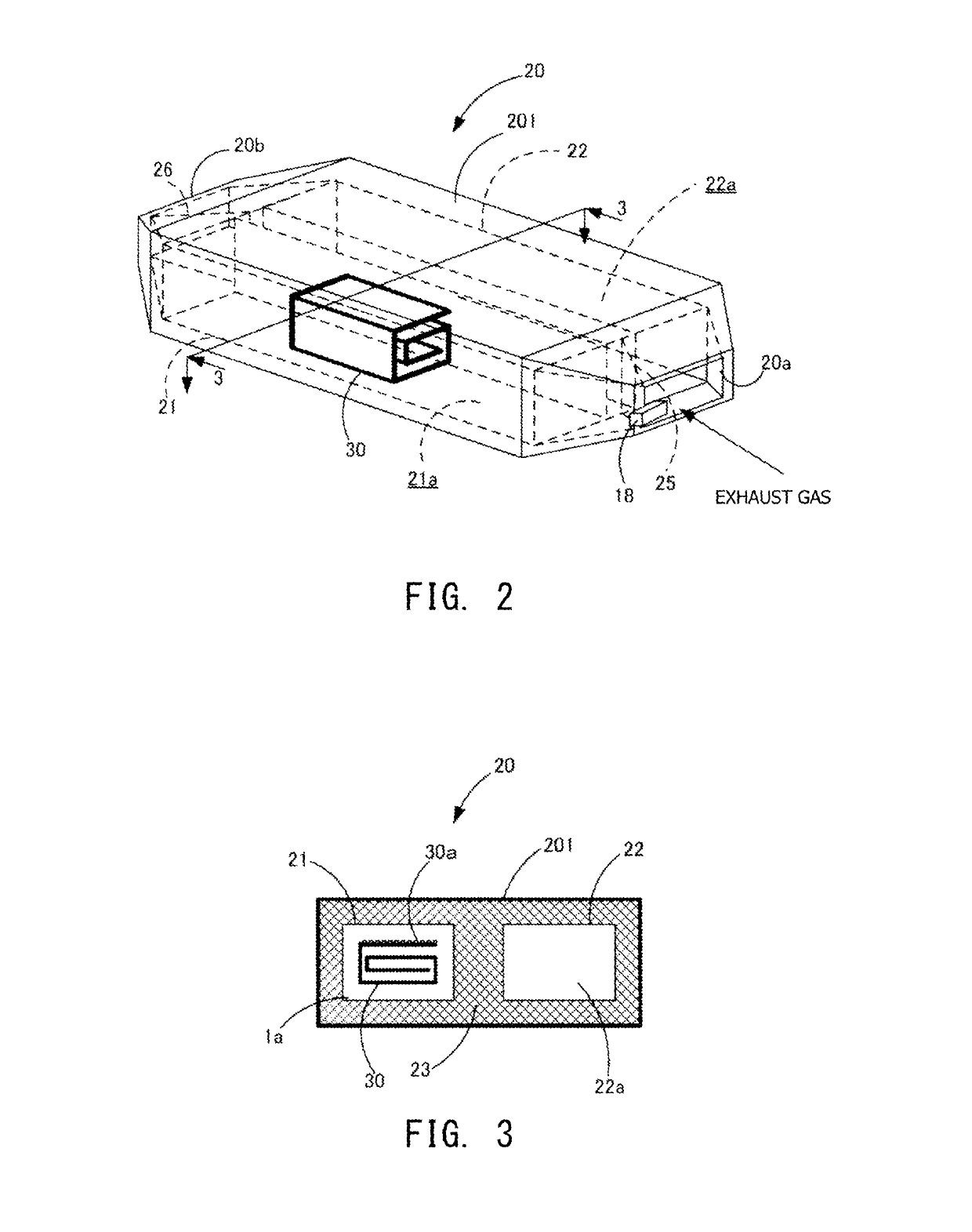
An ammonia generation apparatus is disposed in a stage after a urea water injection unit. The ammonia generation apparatus includes a main body which has an introduction opening for introducing exhaust gas, a discharge opening for discharging the exhaust gas, a first flow passage and a second flow passage which communicate with the introduction opening and the discharge opening and which are separated from each other. The ammonia generation apparatus includes a heating unit disposed in the first flow passage, and a first changeover section which is disposed on one side of the main body where the introduction opening is provided and which can switch the exhaust gas flow passage between the first flow passage and the second flow passage.

Description

[0001]This application claims the benefit of Japanese Patent Applications No. 2015-036509 filed Feb. 26, 2015 and No. 2015-105069 filed May 25, 2015, which are incorporated herein by reference in their entity.FIELD OF THE INVENTION[0002]The present invention relates to an ammonia generation apparatus and an ammonia generation control apparatus.BACKGROUND OF THE INVENTION[0003]In order to cope with recent regulations on the components of emission gas (exhaust gas) of an internal combustion engine, various types of exhaust gas purification units are disposed in the exhaust pipe passage of the internal combustion engine. One of these exhaust gas purification units is a selective catalytic reduction (SCR) unit, which has been known as an apparatus for reducing and purifying NOx. Such an SCR unit reduces and purifies NOx through use of an NOx reducing catalyst and ammonia produced as a result of hydrolysis of urea water serving as a reducing agent. A temperature of about 200° C. is neede...

Claims


Application Information

Patent Timeline
Patent Type & Authority Patents(United States)
IPC IPC(8): F01N3/00B01D53/94F01N3/20C01C1/08F01N13/00
CPCB01D53/9431C01C1/086F01N3/2066F01N13/009B01D53/9495Y02T10/24B01D53/9477B01D2251/2062B01D2251/2067B01D2258/012F01N2240/16F01N2410/00F01N2610/02F01N2610/102F01N2610/105Y02T10/12
Inventor YOSHIKAWA, TAKAYAMORI, KENTAROSUZUKI, HIROYUKI
Owner NGK SPARK PLUG CO LTD
Learn More