Reductant injecting device, exhaust gas processing device and exhaust gas processing method
a technology of injecting device and processing device, which is applied in the direction of machine/engine, mechanical equipment, separation processes, etc., can solve the problems of insufficient ammonia required for nox treatment, difficult reaction of urea, and irregular temperature in the honeycomb structure portion
- Summary
- Abstract
- Description
- Claims
- Application Information
AI Technical Summary
Benefits of technology
Problems solved by technology
Method used
Image
Examples
embodiment 1
(1) Reductant Injecting Device
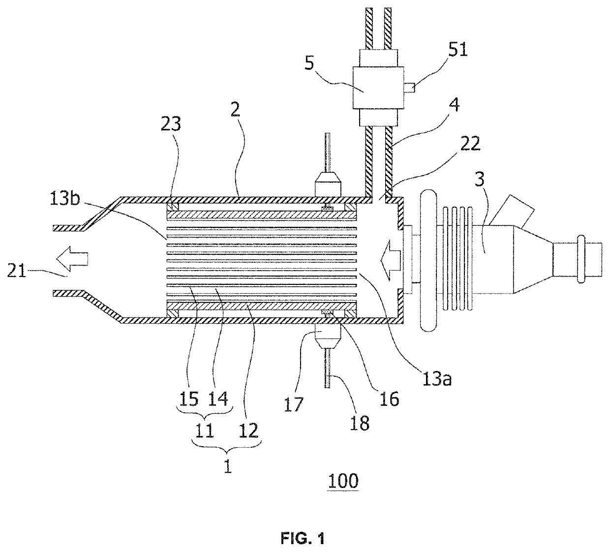
[0039]FIG. 1 is a schematic cross-sectional view showing a reductant injecting device according to Embodiment 1 of the present invention (a schematic cross-sectional view parallel to an extending direction of cells of a honeycomb structure portion).
[0040]As shown in FIG. 1, a reductant injecting device 100 according to the present embodiment includes: a honeycomb structure 1; an outer cylinder 2; a urea sprayer 3; a carrier gas introduction cylinder 4; and a carrier gas flow rate amplifier 5.
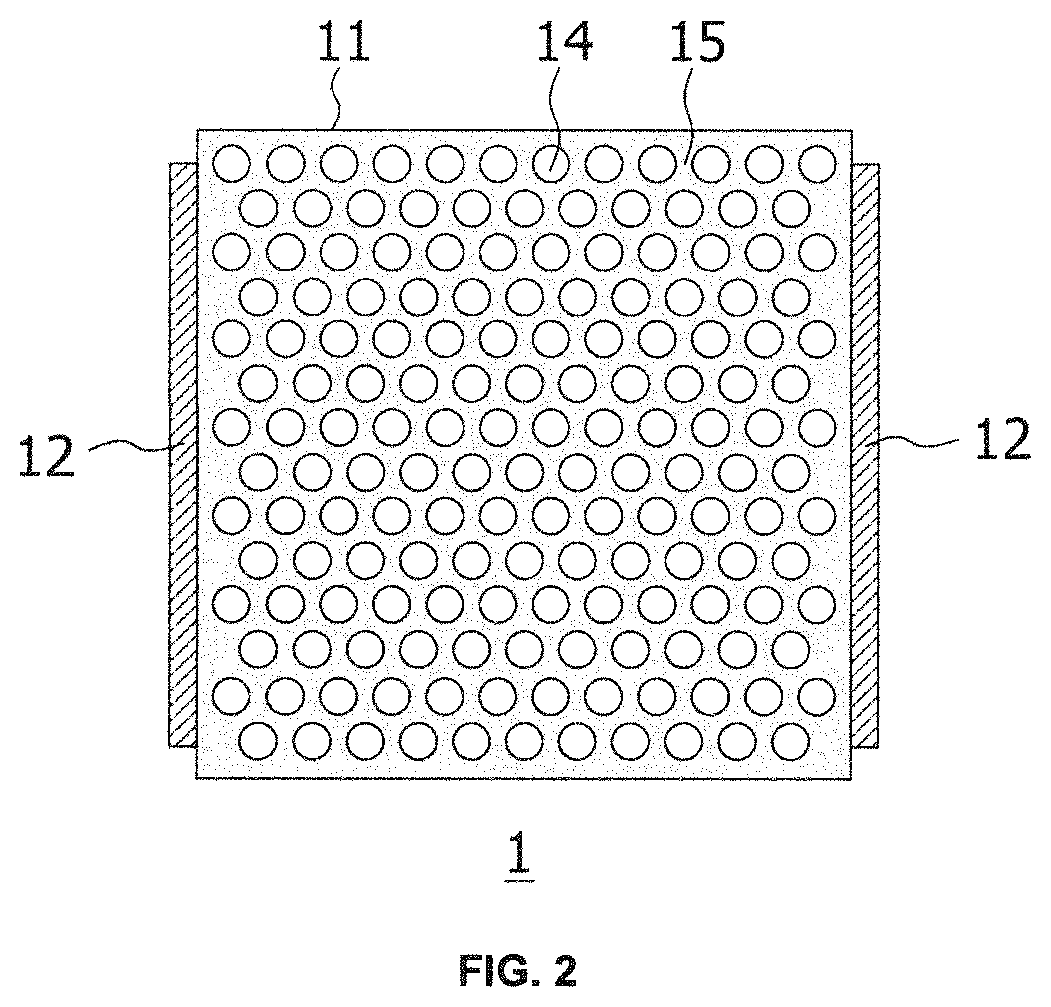
[0041]The honeycomb structure 1 includes: a pillar shaped honeycomb structure portion 11 having a partition wall 15 that defines a plurality of cells 14 extending from a fluid inflow end face 13a to a fluid outflow end face 13b; and at least one pair of electrode portions 12 being configured to heat the honeycomb structure portion 11 by conducting a current, the electrode portions 12 being arranged on a side surface of the honeycomb structure portion 11. The cells 1...
embodiment 2
[0117]FIG. 5 is a schematic cross-sectional view showing a reductant injecting device according to Embodiment 2 of the present invention (a schematic cross-sectional view parallel to an extending direction of cells of a honeycomb structure portion).
[0118]As shown in FIG. 5, a reductant injecting device 200 according to the present embodiment has a different configuration from that of the reductant injecting device 100 according to Embodiment 1 in that the former further includes a urea hydrolysis catalyst body 31 on the fluid outflow end face 13b side of the honeycomb structure portion 11, spaced apart from the fluid outflow end face 13b. Other configurations of the reductant injecting device 200 according to the present embodiment are the same as those of the reductant injecting device 100 according to Embodiment 1. Therefore, descriptions of the other configurations will be omitted, and only differences will be described in detail.
[0119]In the reductant injecting device 200 accord...
embodiment 3
[0122]FIGS. 6 and 7 are schematic cross-sectional views showing exhaust gas processing devices according to Embodiment 3 of the present invention.
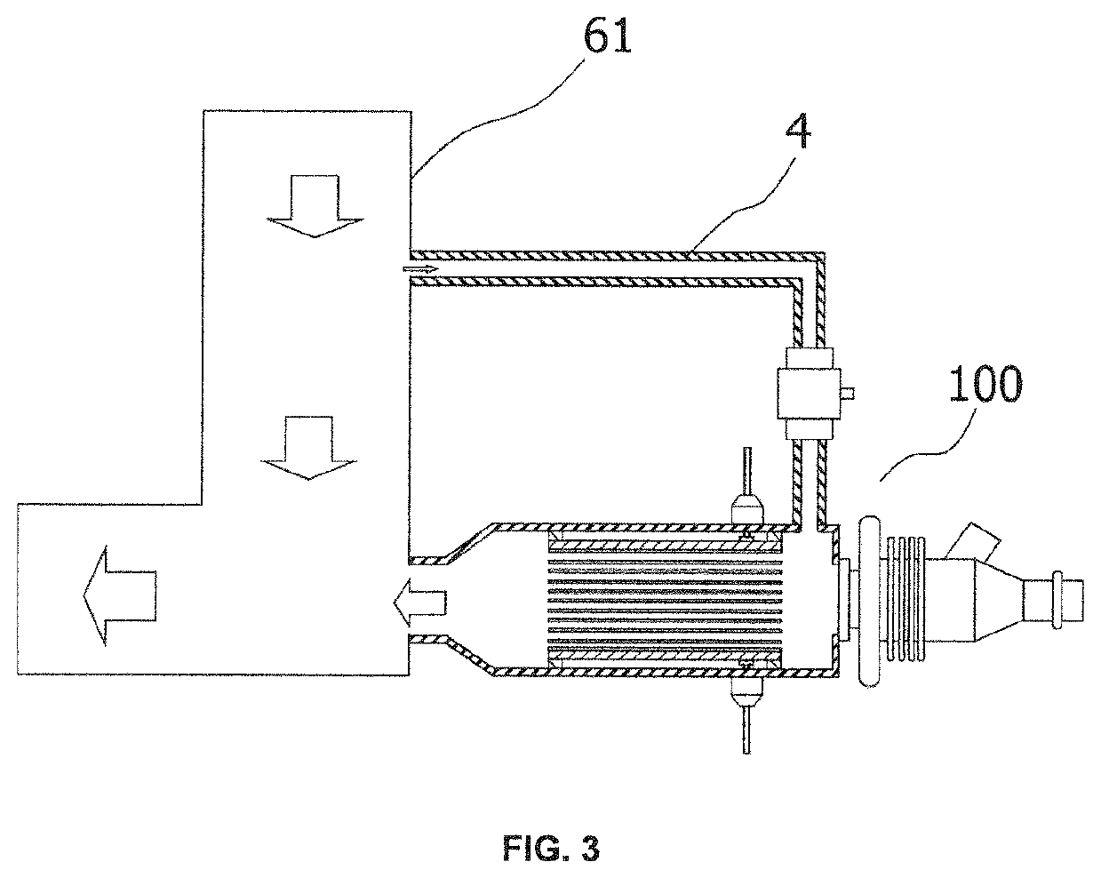
[0123]As shown in FIGS. 6 and 7, each of the exhaust gas processing devices 300, 400 according to the present embodiment include: an exhaust gas pipe 61 through which the exhaust gas flows; the reductant injecting device 100 for injecting the ammonia into the exhaust gas pipe 61; and an SCR catalyst 62 arranged at the exhaust gas pipe 61 on a downstream side of a position where the ammonia is injected.
[0124]The exhaust gas pipe 61 is a pipe through which an exhaust gas (an exhaust gas containing NOx) discharged from various engines and the like is passed, and in which the exhaust gas and ammonia are mixed. The size of the exhaust gas pipe 61 is not particularly limited, and it can be appropriately determined depending on exhaust systems such as engines to which the exhaust gas processing devices 300, 400 according the present embodiment ar...
PUM
 Abstract
Description
Claims
Application Information
 - R&D
- Intellectual Property
- Life Sciences
- Materials
- Tech Scout
- Unparalleled Data Quality
- Higher Quality Content
- 60% Fewer Hallucinations
Browse by: Latest US Patents, China's latest patents, Technical Efficacy Thesaurus, Application Domain, Technology Topic, Popular Technical Reports.
© 2025 PatSnap. All rights reserved.Legal|Privacy policy|Modern Slavery Act Transparency Statement|Sitemap|About US| Contact US: help@patsnap.com


