Capacitance measuring circuit capacitance measuring instrument and microphone device
a capacitance measuring circuit and capacitance measurement technology, applied in the field of circuits and devices, can solve the problems of increasing errors and increasing detection errors, and achieve the effect of reducing noise mixed and reducing stray capacitan
- Summary
- Abstract
- Description
- Claims
- Application Information
AI Technical Summary
Benefits of technology
Problems solved by technology
Method used
Image
Examples
first embodiment
[0029] (First Embodiment)
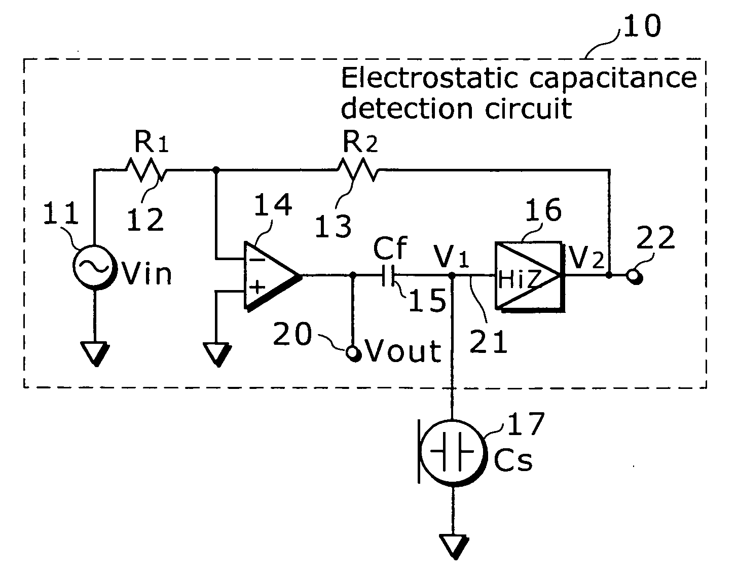
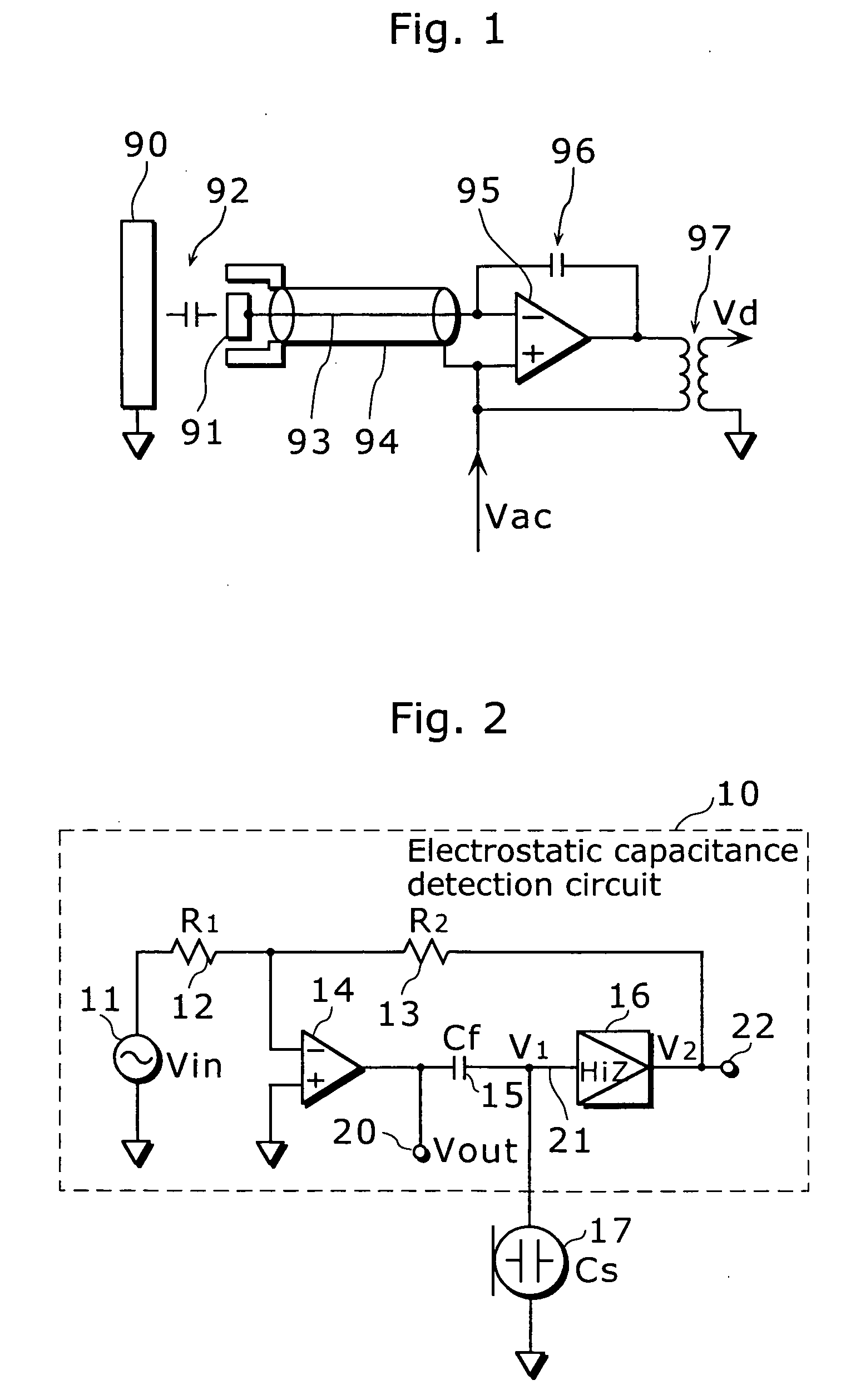
[0030]FIG. 2 is a circuit diagram of an electrostatic capacitance detection circuit 10 according to a first embodiment of the present invention. In this diagram, this electrostatic capacitance detection circuit 10 is connected to a capacitor to be detected 17 that is a subject for detection (i.e. a capacitance type sensor that detects various types of physical quantities using a fluctuation in the electrostatic capacitance Cs such as a capacitor microphone in this example.)
[0031] This electrostatic capacitance detection circuit 10 comprises an AC voltage generator 11 that generates AC voltage, a resistance (R1) 12, a resistance (R2) 13, an operational amplifier 14, an impedance element 15 (a capacitor with capacitance Cf in this example) and an impedance converter 16, and outputs a detection signal (voltage V out) corresponding to electrostatic capacitance of the capacitor 17 from a signal output terminal 20.
[0032] One end of the AC voltage generator 11 is...
second embodiment
[0053] (Second Embodiment)
[0054] The following describes an electrostatic capacitance detection circuit according to a second embodiment of the present invention.
[0055]FIG. 4 is a circuit diagram of an electrostatic capacitance detection circuit 30 in the second embodiment. This electrostatic capacitance detection circuit 30 is roughly composed of a core unit 31 equivalent to the electrostatic capacitance detection circuit 10 shown in FIG. 2, an inverting unit 32 that receives signal voltage V01 at a signal output terminal 20 of the core unit 31 as an input and inverts the signal voltage V01, an adding unit 33 that adds up signal voltage V03 at an output terminal 23 of the inverting unit 32 and signal voltage V02 at an AC output terminal 22 of the core unit 31 and outputs a detection signal of voltage V04 to an output terminal 24.
[0056] The core unit 31 has the same circuit as the electrostatic capacitance detection circuit 10 shown in FIG. 2. Therefore, according to the above exp...
PUM
| Property | Measurement | Unit |
|---|---|---|
| electrostatic capacitance | aaaaa | aaaaa |
| electrostatic capacitance | aaaaa | aaaaa |
| diameter | aaaaa | aaaaa |
Abstract
Description
Claims
Application Information
 - R&D
- Intellectual Property
- Life Sciences
- Materials
- Tech Scout
- Unparalleled Data Quality
- Higher Quality Content
- 60% Fewer Hallucinations
Browse by: Latest US Patents, China's latest patents, Technical Efficacy Thesaurus, Application Domain, Technology Topic, Popular Technical Reports.
© 2025 PatSnap. All rights reserved.Legal|Privacy policy|Modern Slavery Act Transparency Statement|Sitemap|About US| Contact US: help@patsnap.com


