Multi-stage transmission for vehicles

a multi-stage transmission and vehicle technology, applied in mechanical equipment, transportation and packaging, gearing, etc., can solve the problems of increased cost and weight, deterioration of mounting features and transfer efficiency, etc., to achieve simple configuration, improve vehicle silence during driving, and maximize fuel efficiency

Active Publication Date: 2019-06-04
HYUNDAI MOTOR CO LTD +1
View PDF9 Cites 0 Cited by
  • Summary
  • Abstract
  • Description
  • Claims
  • Application Information

AI Technical Summary

Benefits of technology

[0008]Accordingly, the present disclosure has been made keeping in mind the above problems occurring in the related art. The present disclosure is intended to propose a multi-stage transmission for a vehicle, in which ten forward gear ratios and one reverse gear ratio are realized with a small number of components and a comparatively simple configuration, whereby it is possible to maximize fuel efficiency by allowing an engine to be driven at an optimal driving point and is possible to improve silence of the vehicle during driving.
[0017]According to the multi-stage transmission for a vehicle configured as described above, ten forward gear ratios and one reverse gear ratio are realized with a small number of components and a comparatively simple configuration, whereby it is possible to maximize fuel efficiency by allowing an engine to be driven at an optimal driving point and is possible to improve silence of the vehicle during driving.

Problems solved by technology

However, as shifting stages of the transmission are increased, the number of internal components configuring the transmission are increased, such that a mounting feature and transfer efficiency may be deteriorated and a cost and a weight may be increased.

Method used


Image

  • Multi-stage transmission for vehicles
  • Multi-stage transmission for vehicles

Examples


Embodiment Construction

[0021]Hereinbelow, a multi-stage transmission for a vehicle according to an embodiment of the present disclosure will be described in detail with reference to the accompanying drawings.

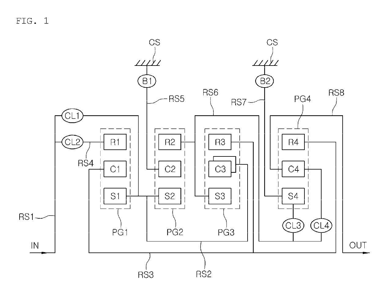
[0022]Referring to FIG. 1, a multi-stage transmission for a vehicle of the present disclosure includes an input shaft IN, an output shaft OUT, a first planetary gear set PG1, a second planetary gear set PG2, a third planetary gear set PG3, and a fourth planetary gear set PG4 provided between the input shaft IN and the output shaft OUT to transfer a torque. Each planetary gear set includes three rotating elements. Six shifting elements are connected to the rotating elements of the first, second, third and fourth planetary gear sets.

[0023]A first rotating element S1 of the first planetary gear set PG1 is fixedly connected to a first rotating element S2 of the second planetary gear set PG2 and a second rotating element C3 of the third planetary gear set PG3 and is selectively connected to the input shaft...


PUM


Abstract

A multi-stage transmission includes an input shaft, an output shaft, a first planetary gear set, a second planetary gear set, a third planetary gear set, and a fourth planetary gear set. Each planetary gear set includes three rotating elements. Six shifting elements are connected to the rotating elements of the first, the second, the third and the fourth planetary gear sets. A first rotating element of the first planetary gear set is fixedly connected to a first rotating element of the second planetary gear set and a second rotating element of the third planetary gear set and is selectively connected to the input shaft. A second rotating element thereof is fixedly connected to a third rotating element of the third planetary gear set and a third rotating element of the fourth planetary gear set. A third rotating element thereof is selectively connected to the input shaft.

Description

CROSS REFERENCE TO RELATED APPLICATION[0001]The present application claims priority to Korean Patent Application No. 10-2017-0119339, filed Sep. 18, 2017, the entire contents of which is incorporated herein for all purposes by this reference.BACKGROUNDField of the Disclosure[0002]The present disclosure relates generally to a multi-stage transmission for a vehicle. More particularly, the present disclosure relates to a technology capable of improving fuel efficiency of a vehicle by implementing as many shifting stages as possible with as few components as possible and in as simple a configuration as possible.Description of the Related Art[0003]Recently, a rise in oil prices has become a factor pushing automobile manufacturers throughout the world to enter into unlimited competition to improve fuel efficiency. In the case of an engine, efforts have been made to improve fuel efficiency and decrease weight through technology such as downsizing, or the like.[0004]Various methods of impro...

Claims


Application Information

Patent Timeline
Patent Type & Authority Patents(United States)
IPC IPC(8): F16H3/66
CPCF16H3/66F16H2200/2046F16H2200/2012F16H2200/0069F16H3/666F16H2003/445
Inventor KWON, HYUN SIKJI, SEONG WOOKPARK, JU HYEONYOO, IL HANHWANG, SEONG WOOKKIM, KI TAE
Owner HYUNDAI MOTOR CO LTD
Why Eureka
Try Eureka