
Transaxle for a vehicle

a transaxle and vehicle technology, applied in mechanical devices, transportation and packaging, gear production, etc., can solve the problems of limited compactness of the engine, time-consuming and expensive, and the inability to improve the compactness of the transaxle, so as to reduce the noise of forward travel and compact the effect of configuration

Inactive Publication Date: 2008-03-20
KAWASAKI HEAVY IND LTD
View PDF2 Cites 0 Cited by
  • Summary
  • Abstract
  • Description
  • Claims
  • Application Information

AI Technical Summary

Benefits of technology

[0012]The present invention addresses the above described conditions, and an object of the present invention is to provide a transaxle for a vehicle which is capable of reducing noise during forward travel and has a compact configuration.
[0013]According to the present invention, there is provided a transaxle for a vehicle comprising: a transaxle casing; an input shaft housed in the transaxle casing, the input shaft being configured to receive as an input a driving power from an engine of the vehicle; an intermediate shaft housed in the transaxle casing so as to extend parallel to the input shaft; an axle housed in the transaxle casing so as to extend parallel to the intermediate shaft, the axle being configured to drive a rear wheel of the vehicle; a rearward travel gear mechanism which is mounted between the input shaft and the intermediate shaft and is configured to transmit the driving power for traveling the vehicle rearward from the input shaft to the intermediate shaft; a forward travel chain mechanism configured to transmit the driving power for moving the vehicle forward from the input shaft to the intermediate shaft; and a transmission gear mechanism which is mounted between the intermediate shaft and the axle and is configured to transmit the driving power from the intermediate shaft to the axle. In accordance with such a configuration, since the driving power for forward travel is transmitted via the chain, silence of the transaxle in the forward travel can be improved. In addition, since the driving power for forward travel of the vehicle is transmitted via the chain, the intermediate shaft is rotated in the same direction as the input shaft, and the axle that is applied with the driving power from the intermediate shaft via the transmission gear mechanism is rotated in an opposite direction to the rotation of the input shaft. Therefore, in the transaxle, to which the driving power is transmitted via a CVT from a general purpose engine which is positioned forward of the transaxle and rotates counterclockwise, when the engine is seen from an output shaft side of the engine, the axle can be rotated clockwise which is an opposite direction to the rotation of the input shaft with the input shaft being rotated counterclockwise (the same direction to the rotation of the engine) during forward travel when the transaxle is seen from rightward (input side of the input shaft). During rearward travel, the intermediate shaft is rotated in the opposite direction to the rotation of the input shaft by a rearward travel gear mechanism, and the axle coupled to the intermediate shaft via the transmission gear mechanism is rotated in the opposite direction to the rotation of the intermediate shaft, i.e., counterclockwise from rightward. Thus, a compact transaxle including three shafts for performing gear reduction in two stages in both forward travel and rearward travel can be achieved.
[0014]The forward travel chain mechanism may include a silent chain. This makes it possible to improve noise reduction of the chain.
[0015]The silent chain may be a double chain or more. With the use of a silent chain with a small pitch, it becomes possible to suppress rotation variation that may occur on a downstream side when the double chain is used to transmit driving power. Thus, noise reduction can be improved.
[0016]A center axis of the intermediate shaft may be positioned below a straight line connecting a center axis of the input shaft to a center axis of the axle. This makes it possible to easily feed oil from an oil reservoir in the interior of the transaxle casing to the intermediate shaft.
[0017]The forward travel chain mechanism may be configured to be subjected to oil bath lubrication such that a part of the forward travel chain mechanism is immersed in oil in an oil reservoir provided at a bottom portion of the transaxle casing. This makes it possible to improve durability of the chain, and to reduce labor required to maintain and inspect the transaxle mounted in a narrow space of a vehicle body of the low-speed vehicle.

Problems solved by technology

So, gear production has been time-consuming and expensive.
Furthermore, since the engine is limited in improving compactness, improving compactness of the transaxle is an important issue at present.

Method used


Image

  • Transaxle for a vehicle
  • Transaxle for a vehicle
  • Transaxle for a vehicle

Examples


Embodiment Construction

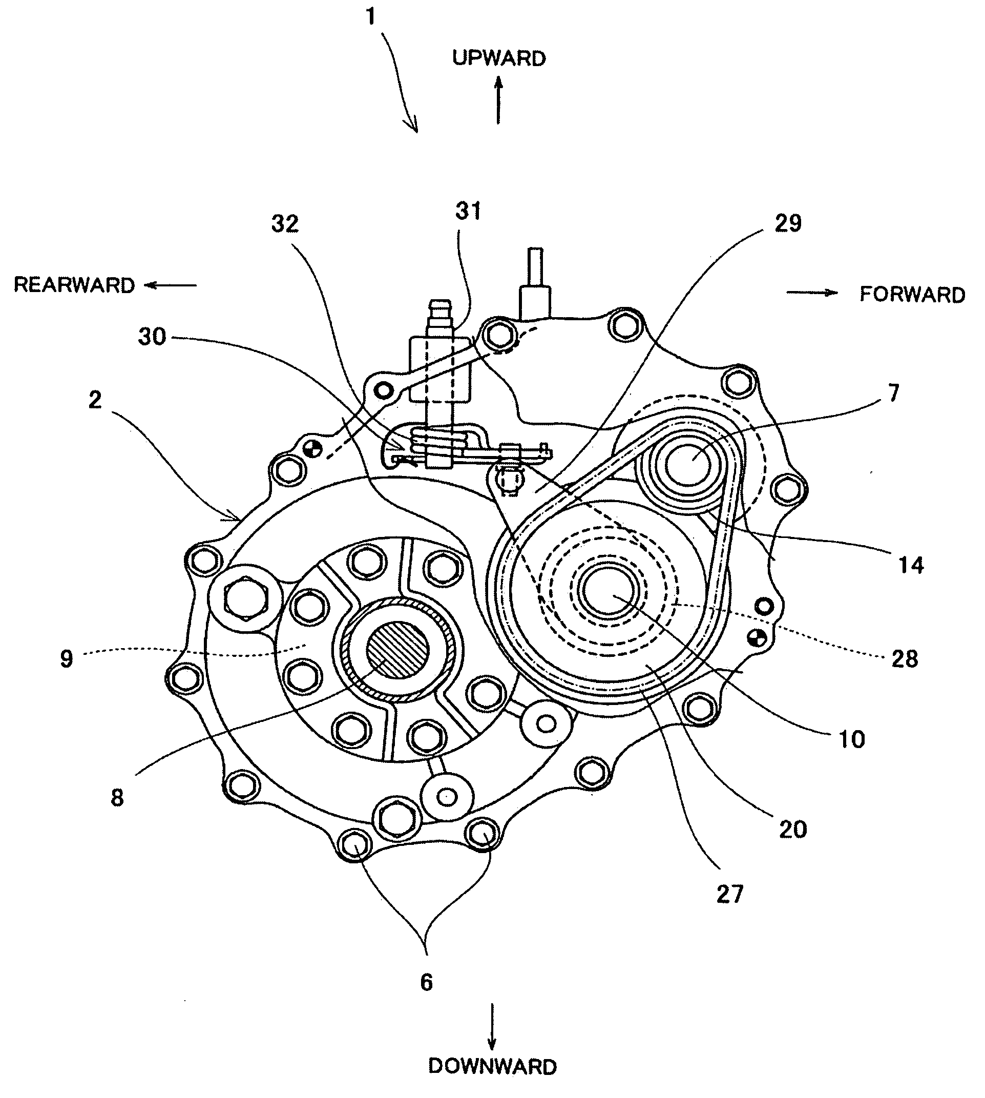
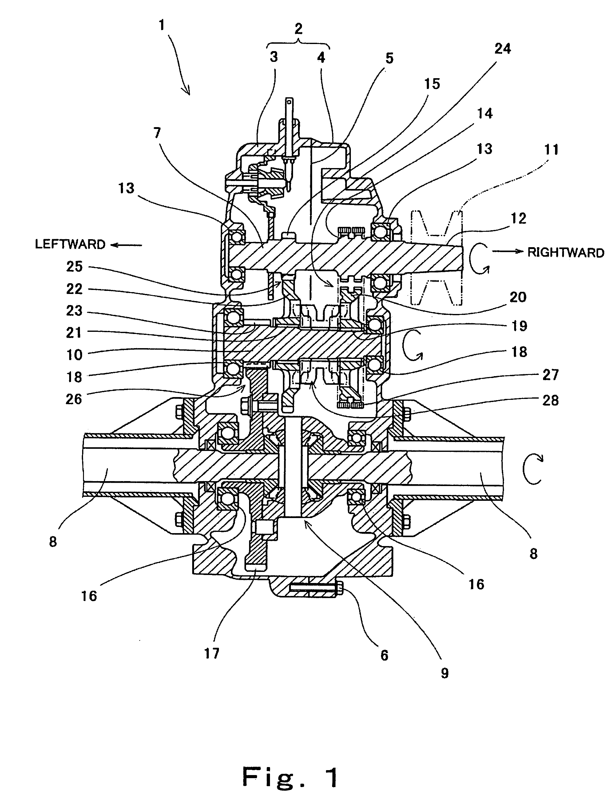
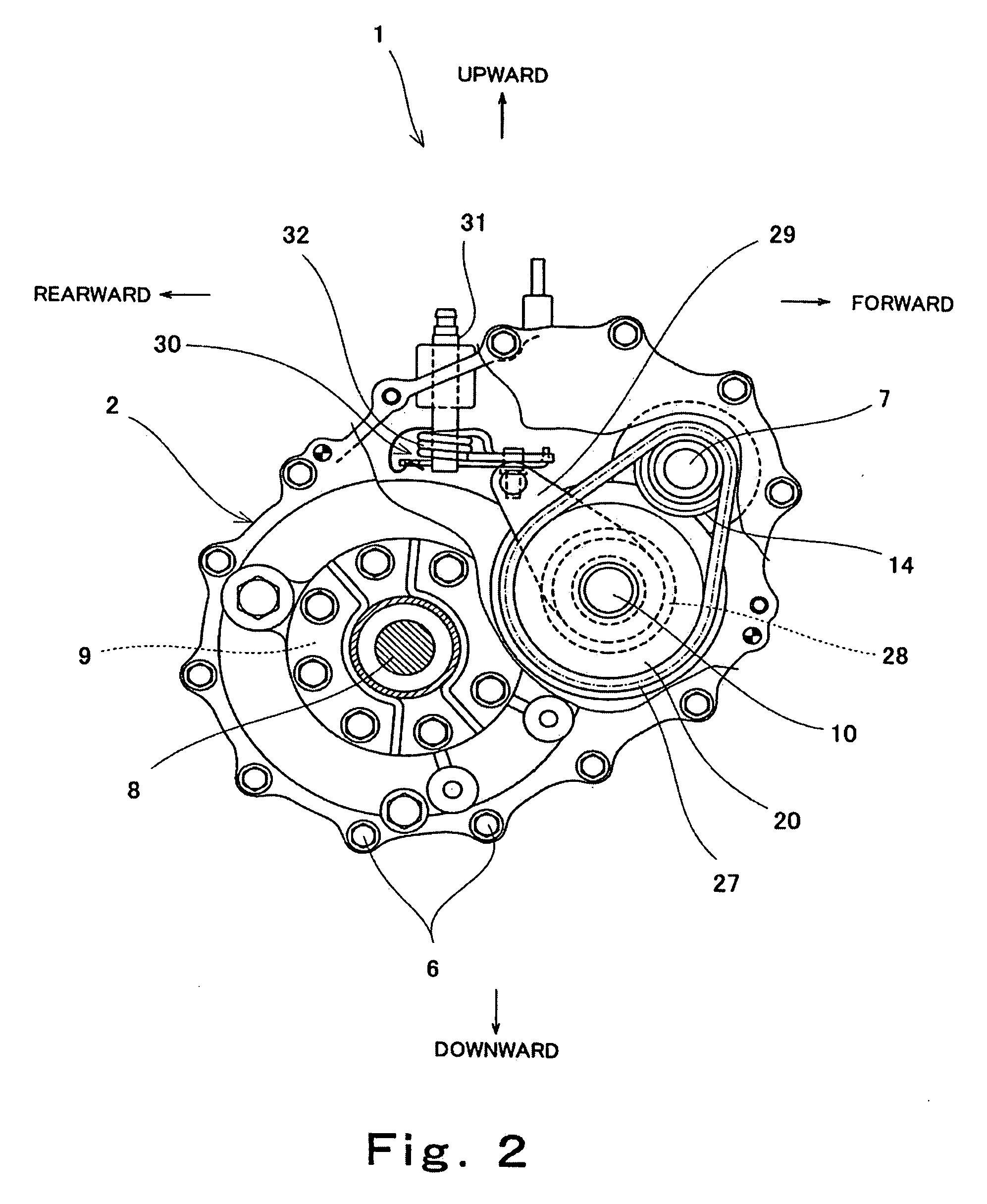
[0025]Hereinafter, an embodiment of the present invention will be described with reference to the drawings. FIG. 1 is an exploded cross-sectional view showing a transaxle for a vehicle according to an embodiment of the present invention, including center axes of respective shafts of the transaxle. FIG. 2 is a side view showing a partial cross-section of the transaxle for the vehicle of FIG. 1. In FIG. 1, arrows indicate rotational directions during forward travel. As used herein, the rotational direction of the shafts which is viewed from an input side (rightward in FIG. 1) of an input shaft 7 of the transaxle 1 in the state shown in FIG. 1 is referred to as clockwise or counterclockwise. Also, the directions are referenced from the perspective of a rider riding in the vehicle of FIG. 1 except as where otherwise specifically described or illustrated.

[0026]As shown in FIG. 1, a transaxle casing 2 of the transaxle 1 includes a pair of right and left casing members 3 and 4. The casing ...


PUM


Abstract

A transaxle for a vehicle comprises a transaxle casing; an input shaft housed in the transaxle casing and configured to receive as an input a driving power from an engine of the vehicle; an intermediate shaft housed in the transaxle casing; an axle housed in the transaxle casing and configured to drive a rear wheel of the vehicle; a rearward travel gear mechanism which is mounted between the input shaft and the intermediate shaft and is configured to transmit the driving power for moving the vehicle rearward from the input shaft to the intermediate shaft; a forward travel chain mechanism configured to transmit the driving power for moving the vehicle forward from the input shaft to the intermediate shaft; and a transmission gear mechanism which is mounted between the intermediate shaft and the axle and is configured to transmit the driving power from the intermediate shaft to the axle.

Description

TECHNICAL FIELD[0001]The present invention relates to a transaxle typically equipped in a low-speed vehicle, and particularly to a transaxle for a vehicle which is suitable for use with a low-speed vehicle such as a golf cart or a utility vehicle.BACKGROUND ART[0002]As examples of engine-driven low-speed vehicles which travel at relatively low speeds, there are golf carts, utility vehicles, and others, which are hereinafter collectively referred to as low-speed vehicles. In these low-speed vehicles, a transaxle reduces the speed of a driving power of the engine and rotates its axles with the reduced speed. The transaxle also has a rearward travel function and is configured to be able to switch between forward travel and rearward travel by switching a shift sleeve.[0003]A driving unit which is typically equipped in a low-speed vehicle, for example, a golf cart, will be described with reference to FIG. 3. FIG. 3 is a plan view showing in perspective a driving system for a golf cart 51...

Claims


Application Information

Patent Timeline
Patent Type & Authority Applications(United States)
IPC IPC(8): F16H37/08
CPCB60K17/08B60Y2200/86Y10T74/19223F16H9/24F16H3/14
Inventor ODA, KAORUMORITA, TAISUKETAKAGI, IZUMI
Owner KAWASAKI HEAVY IND LTD
Learn More