
Image capturing device with high image sensing coverage rate and related image capturing method

a technology of image sensing and image capturing device, which is applied in the field of image capturing device, can solve the problems of waste of user attention, unconcerned image information about ceiling, wall and ground, and ineffective in the actual application of image monitoring operation, so as to achieve the effect of increasing the image sensing coverage rate of the image capturing devi

Active Publication Date: 2019-06-04
VIVOTEK INC
View PDF6 Cites 0 Cited by
  • Summary
  • Abstract
  • Description
  • Claims
  • Application Information

AI Technical Summary

Benefits of technology

The present invention is an image sensing unit that is combined with an optical lens component. The imaging circle of the optical lens component can align with the edges of the sensing region, creating an overlapping area that exceeds 180 degrees. This design allows for a wide field of view and high image resolution. The unique position of the imaging circle in relation to the sensing region allows for optimal image quality and coverage. The technical effect is an increased number of pixels and improved image quality for a given camera size and position.

Problems solved by technology

The image monitoring system is generally disposed on the ceiling, the wall or the ground, and image information about the ceiling, the wall and the ground are unconcerned or useless in actual application of the image monitoring operation, or is in no need of monitoring.
Due to the assembling constraint and property effect of the fisheye lens, the conventional panoramic camera device cannot capture sufficient image information about the major monitoring region within mostly actual applied environment, certain image information (such as the image covering the ceiling, the wall or the ground) which is unmindful by the user is wasted, and the image sensor does not provide optimal ability.
Therefore, design of adjusting relation between the camera lens and the image sensor of the image monitoring system to increase an image sensing coverage rate and to maximize a usage region of the image sensor for gaining the needed image information within restricted hardware resource is an important issue in the related monitoring industry.

Method used


Image

  • Image capturing device with high image sensing coverage rate and related image capturing method
  • Image capturing device with high image sensing coverage rate and related image capturing method
  • Image capturing device with high image sensing coverage rate and related image capturing method

Examples


Embodiment Construction

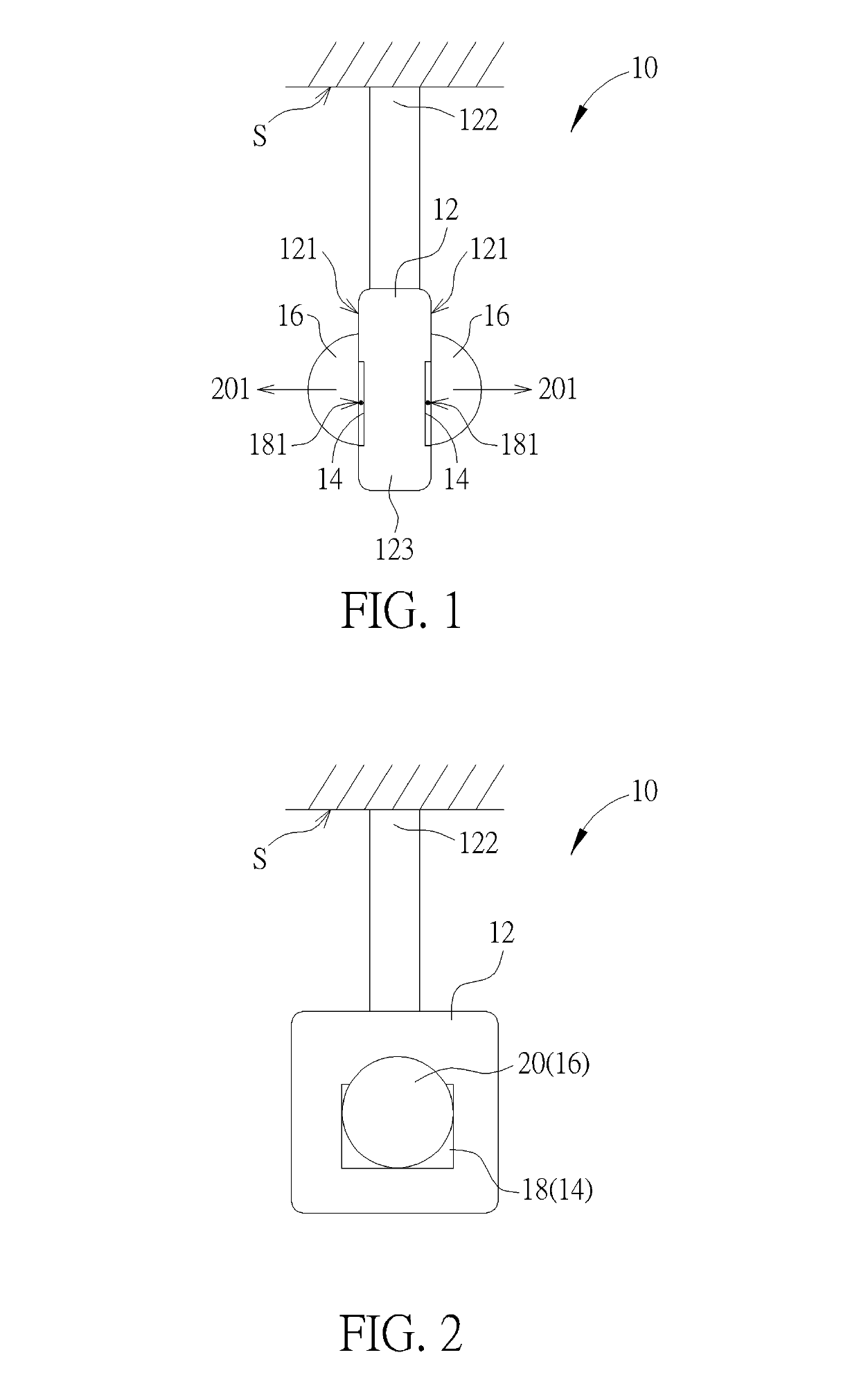
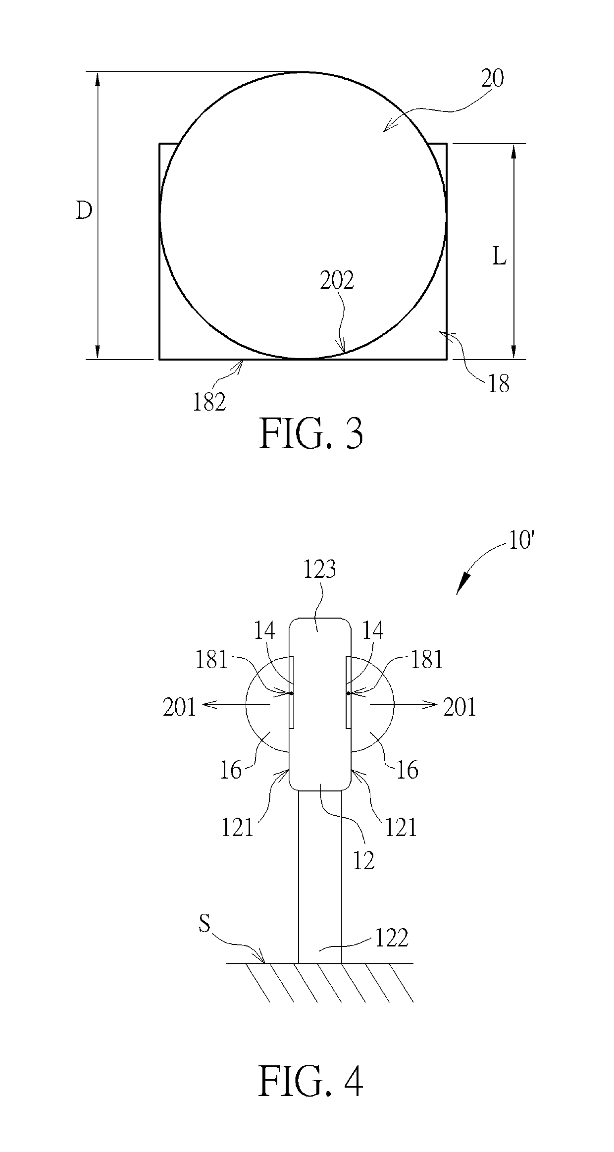
[0015]Please refer to FIG. 1 to FIG. 3. FIG. 1 is a lateral view of an image capturing device 10 according to a first embodiment of the present invention. FIG. 2 is a front view of the image capturing device 10 according to the first embodiment of the present invention. FIG. 3 is a diagram of a sensing region 18 and an imagery circle 20 overlapped with each other according to the first embodiment of the present invention. The image capturing device 10 can include a base 12, an image sensing unit 14 and an optical lens component 16. The image sensing unit 14 has a sensing region 18 utilized for capturing an image. An amount of the image sensing unit 14 can be one or more, and the image sensing units 14 can be respectively disposed on corresponding lateral surfaces 121 on the base 12. The optical lens component 16 has an imagery circle 20, and an amount of the optical lens component 16 is equal to the amount of the image sensing unit 14. The optical lens component 16 can be disposed o...


PUM


Abstract

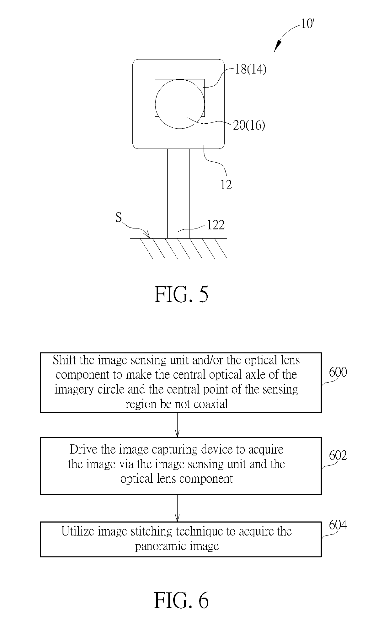
An image capturing device with high image sensing coverage rate is applied by a related image capturing method. The image capturing device includes a base, an image sensing unit and an optical lens component. The image sensing unit is disposed on a lateral surface of the base, and has a sensing region. The optical lens component is overlapped with the image sensing unit, and has an imagery circle. A central optical axle of the imagery circle does not align with a central point of the sensing region; wherein the image capturing device captures an image via the optical lens component and the imaging sensing unit.

Description

BACKGROUND OF THE INVENTION1. Field of the Invention[0001]The present invention relates to an image capturing device and a related image capturing method, and more particularly, to an image capturing device and a related image capturing method with high image sensing coverage rate.2. Description of the Prior Art[0002]The panoramic camera device has wide-angle monitoring function with blind corner and is extensively used as main equipment in the current image monitoring system. One of the panoramic camera devices has a plurality of photograph lenses arranged as a circle, the photograph lenses respectively capture its own images, and the said images are stitched to acquire a panoramic image for the panoramic monitoring function. The other kind of the panoramic camera device utilizes two opposite fisheye lenses to capture fisheye images, and the fisheye images are stitched to acquire the panoramic image containing 360 degrees view region. The image monitoring system is generally dispos...

Claims


Application Information

Patent Timeline
Patent Type & Authority Patents(United States)
IPC IPC(8): G03B37/04H04N5/232G02B13/06G02B13/18H04N5/225
CPCG03B37/04G02B13/06H04N5/23238H04N5/2254H04N5/2258G02B13/18H04N23/45H04N23/55H04N23/698
Inventor WU, JEN-CHIH
Owner VIVOTEK INC
Learn More