Bracket mount for securing micro-inverters and power optimizers to solar panel arrays

a technology for solar panel arrays and brackets, applied in the direction of electric variable regulation, process and machine control, instruments, etc., can solve the problems of low device profile, difficult installation of solar panel arrays on roofs, and known prior art that does not enable micro-inverters and power optimizers to be both secured directly to solar panel frames

Active Publication Date: 2019-06-04
IRONRIDGE
View PDF22 Cites 11 Cited by
  • Summary
  • Abstract
  • Description
  • Claims
  • Application Information

AI Technical Summary

Benefits of technology

[0016]It is a further object of the present invention to provide a method for securing the power optimizer or the micro inverter to a solar panel frame.

Problems solved by technology

Installing a solar panel array on a roof can be challenging.
One difficult aspect of the process is installing micro inventors and power optimizers as part of the array so that these devices have a low profile and require only a minimum number of parts to complete the installation.
The known prior art does not enable micro-inverters and power optimizers to be both secured directly to solar panel frames and electrically bond them to the solar panel array.

Method used


Image

  • Bracket mount for securing micro-inverters and power optimizers to solar panel arrays
  • Bracket mount for securing micro-inverters and power optimizers to solar panel arrays
  • Bracket mount for securing micro-inverters and power optimizers to solar panel arrays

Examples


Embodiment Construction

[0033]In the following description, and for the purposes of explanation, numerous specific details are provided to thoroughly understand the various aspects of the invention. It will be understood, however, by those skilled in the relevant arts, that the present invention may be practiced without these specific details. In other instances, known structures and devices are shown or discussed more generally in order to avoid obscuring the invention. In many cases, a description of the operation is sufficient to enable one to implement the various forms of the invention, particularly when the operation is to be implemented in software. It should be noted that there are many different and alternative configurations, devices and technologies to which the disclosed embodiments may be applied. The full scope of the invention is not limited to the example(s) that are described below.

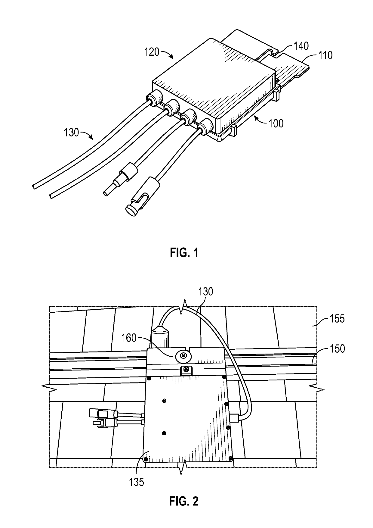
[0034]FIG. 1 shows a typical electrical panel as an exemplary power optimizer 100. As stated previously, a po...


PUM


Abstract

In various representative aspects, an assembly for connecting and electrically bonding electronic equipment to solar panel frames is provided. More specifically, the present invention relates generally to an assembly for securing and installing micro inverter and power optimizer units for use with solar panel arrays that are typically installed on roof structures. The assembly comprises a bracket assembly that couples micro invertors and power optimizers to solar panel frames.

Description

BACKGROUND OF INVENTIONField of the Invention[0001]The present invention relates generally to an assembly for securing and installing electrical panels, and in particular, micro inverter and power optimizer units for use with solar panel arrays that are typically installed on roof structures. More specifically, the assembly comprises a bracket assembly that couples micro invertors and power optimizers to solar panel frames. When coupled to the solar panel frame, the bracket can also include an electrical bonding means to electrically bond the micro invertors and power optimizers to the solar panel frame. A method of installation is also disclosed.Description of the Related Art[0002]Any discussion of the prior art in the specification should in no way be considered as an admission that the prior art is widely known or forms part of common general knowledge in the field.[0003]Installing a solar panel array on a roof can be challenging. One difficult aspect of the process is installing...

Claims


Application Information

Patent Timeline
Patent Type & Authority Patents(United States)
IPC IPC(8): H02S40/34H02S40/32G05F1/67H02M7/00H02S30/00F16B3/00F16B1/00F16B5/06
CPCH02S40/34G05F1/67H02M7/003H02S40/32H02S30/00F16B2001/0064F16B3/00F16B5/0642Y02E10/50Y02B10/10F16B2200/93
Inventor LESTER, BRYANPEREIRA, WILLIAMMEINE, SHAWN
Owner IRONRIDGE
Why Eureka
Try Eureka