Torque indication wrench

a torque indication and wrench technology, applied in the field of torque indication wrenches, can solve the problems of user harm, failure and inability to meet the convenience of storag

Active Publication Date: 2019-06-11
HU BOBBY
View PDF14 Cites 0 Cited by
  • Summary
  • Abstract
  • Description
  • Claims
  • Application Information

AI Technical Summary

Benefits of technology

[0009]For improving the issues above, a torque indication wrench is disclosed. With the general profile performed in a pen shape, the consumed space is reduced, thus meeting the convenience of portability and storage.
[0026]With such configuration, besides the function for allowing the user to directly read the indicated torque value, with the torque rod biasedly disposed against the main body, the torque rod is wrenched from the counterclockwise area of the main body toward the clockwise area during the operation, thus ensuring that the torque indication wrench is generally maintained in a pen shape facilitating the space saving demand and advantageously meeting the convenience of storage and portability.

Problems solved by technology

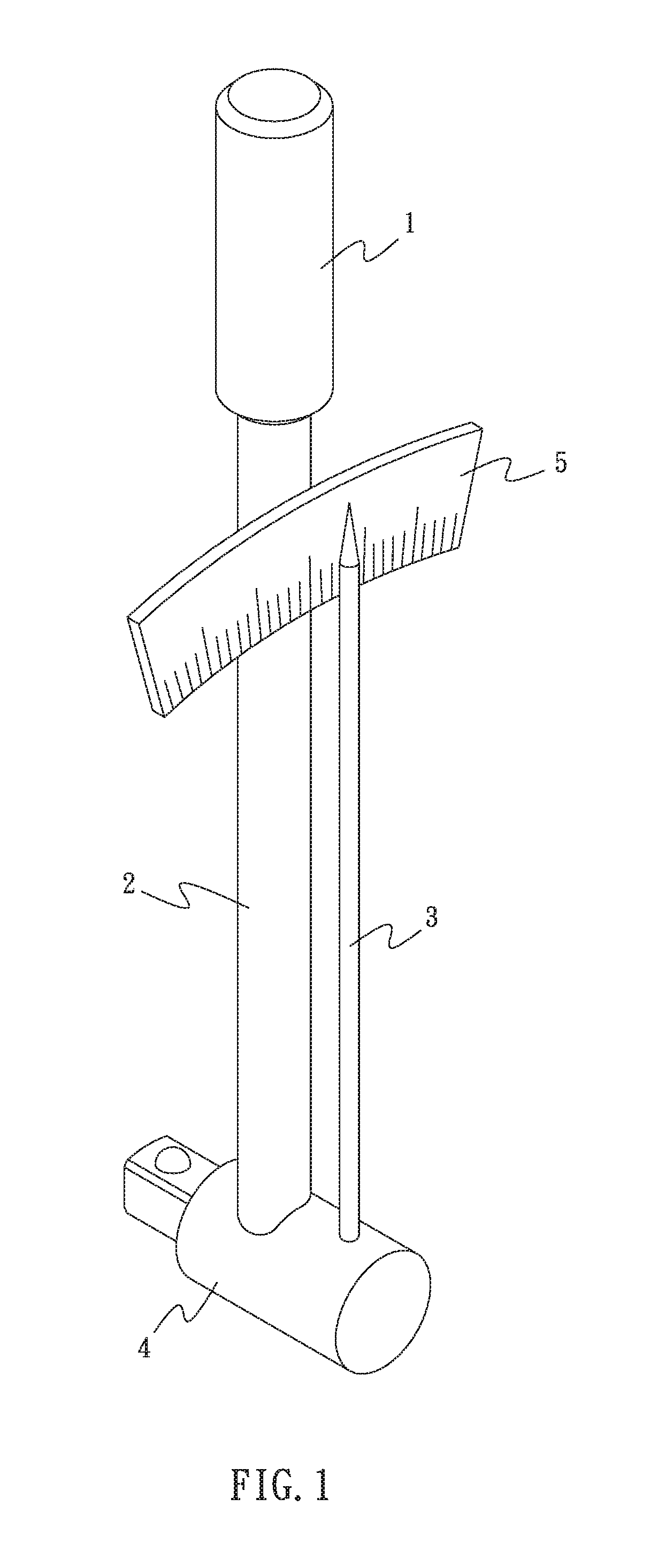
However, the pointer 3 may possibly cause harm upon the user.
Also, the transversely disposed scale plate 5 occupies a relatively large space, failing to meet the convenience of storage.
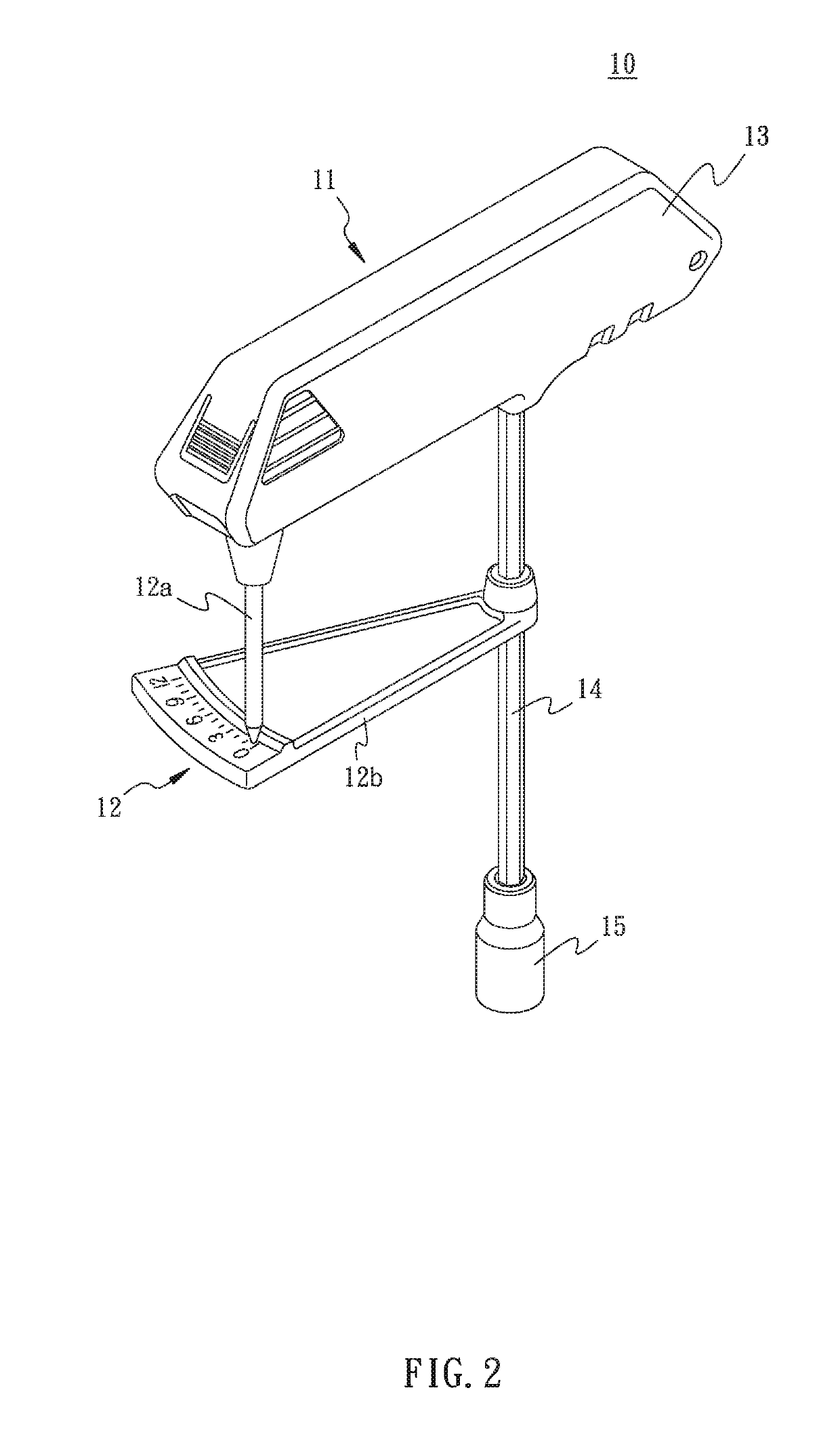
However, the pointer 12a on such torque wrench 10 may still cause harm to the user.
Hence, the torque wrench 10 consumes a relatively large space, failing to meet the convenience or portability and storage.
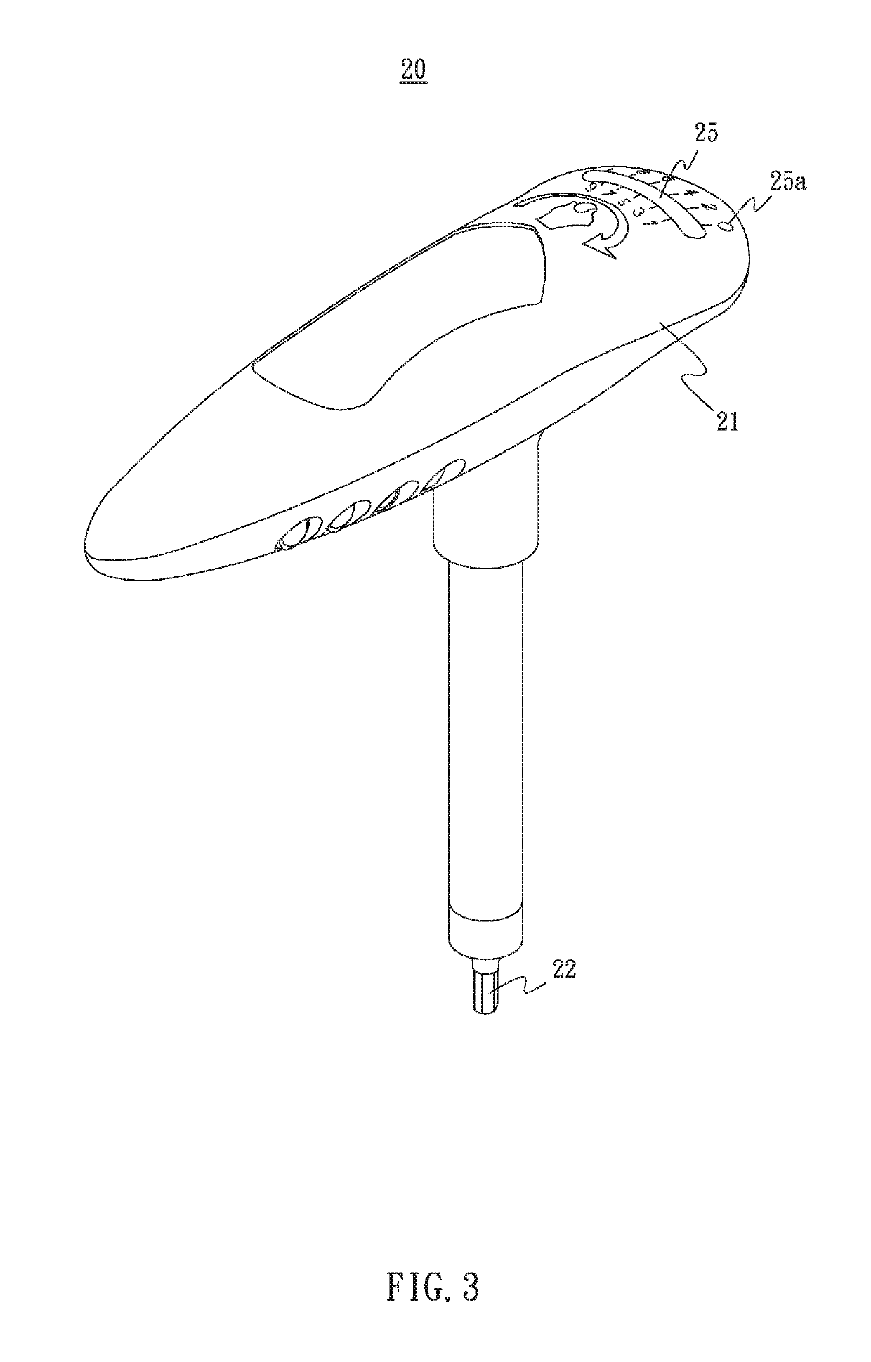
However, the general shape of the torque wrench 20 remains in a T shape, causing a similar issue of being unfavorable to portability and storage.
However, due to the narrow angle of swaying, the scales allowed to be pointed out are limited, such that the user is prevented from efficiently identify the torque level.

Method used


Image

  • Torque indication wrench
  • Torque indication wrench
  • Torque indication wrench

Examples


Embodiment Construction

[0038]The aforementioned and further advantages and features of the present invention will be understood by reference to the description of the preferred embodiment in conjunction with the accompanying drawings where the components are illustrated based on a proportion for explanation but not subject to the actual component proportion. Embodiments of the present invention are illustrated in detail along with the drawings. However, the technical features included by the present invention are not limited to certain embodiments hereby provided. Scope of the present invention shall be referred to the claims, which include all the possible replacements, modifications, and equivalent features.

[0039]Referring to FIG. 5 to FIG. 11, the torque indication wrench 100 comprises a main body 30, a torque rod 40, and an indication device 50.

[0040]The main body 30 comprises a wrenching portion 31 and a support portion 32 connected with the wrenching portion 31. The wrenching portion 31 is allowed t...


PUM


Abstract

A torque indication wrench includes a main body having a wrenching portion and a support portion, a torque rod having a first end and a second end, and an indication device disposed between the main body and the torque rod. The wrenching portion drives an object. The first end is connected with the support portion. The main body defines a longitudinal line dividing the torque into a counterclockwise and an opposite clockwise areas. A biasing section is formed between the first and second ends, with the central axis of the biasing section positioned in the counterclockwise area. The user wrenches the second end of the torque rod, such that the biasing section of the torque rod resiliently bends from the counterclockwise area toward the clockwise area, and the user is able to read an indicated torque value.

Description

BACKGROUND OF THE INVENTION1. Field of the Invention[0001]The present invention relates to small sized torque wrenches, and more particularly, to a torque wrench requiring only limited operational space.2. Description of the Related Art[0002]Referring to FIG. 1, a conventional fine-tunable torque wrench comprises a shaft 1, an operation rod 2, a pointer 3, an operation head 4, and a scale plate 5. The shaft 1 and the operation head 4 are disposed on two ends of the operation rod 2, with the scale plate 5 fixed to the operation rod 2. The pointer 3 has one end thereof attached to the operation head 4, with the other end thereof pointing to the scale plate 5. When a force is imposed on the shaft 1, the operation rod 2 is bent due to the force while the pointer 3 keeps being straight. Therefore, the user learns the torque value by reading the scales on the scale plate 5 pointed by the pointer 3.[0003]However, the pointer 3 may possibly cause harm upon the user. Also, the transversely d...

Claims


Application Information

Patent Timeline
Patent Type & Authority Patents(United States)
IPC IPC(8): B25B23/142
CPCB25B23/1427
Inventor HU, BOBBY
Owner HU BOBBY
Why Eureka
Try Eureka