
Anti-surge structure built in switches

a technology of anti-surge structure and switch, which is applied in the direction of overvoltage protection resistors, resisitors with sliding contact, emergency protective arrangements for limiting excess voltage/current, etc., can solve the problems of inability to protect devices, structure requires more constructing space and procedures, and structure requires more construction space and procedures. , the effect of simple structur

Inactive Publication Date: 2019-10-15
WANG YI HSIANG +1
View PDF13 Cites 0 Cited by
  • Summary
  • Abstract
  • Description
  • Claims
  • Application Information

AI Technical Summary

Benefits of technology

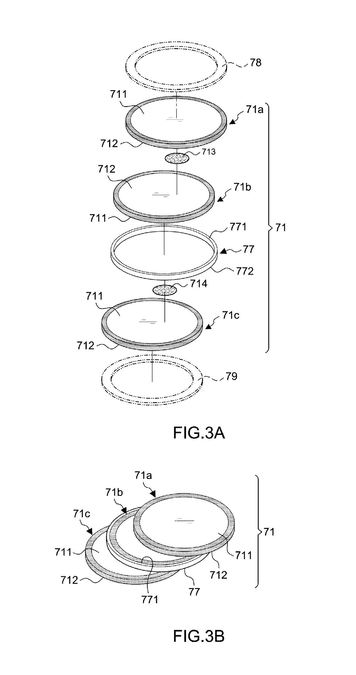
The present invention provides an anti-surge structure in a stair-like arrangement built in switches that retains a function of over-current protection. The structure includes a plurality of metal-oxide varistors in stair-like arrangement with a vertical surface for electrical connection. This prevents the entire structure from high voltage flashover and allows for easier electrical connection without consuming more space. The metal-oxide varistors have the same electrodes for operation and are protected from external impact. Overall, this invention has a simple structure with a shortened height and is perfectly insulated and fixed in position.

Problems solved by technology

However, the structure disclosed above aims at protection from overcurrent situation but is not able to protect the device when sudden overvoltage such as lightning strike occurs.
In short, such structure has shortcomings of uncertain quality, exceeding heat due to external connection of the components, slow reaction, large volume and complicated composition, and the structure requires more constructing space and procedures.
However, the metal-oxide varistors being disposed separately and parallel would increase a height of the structure and result in poor insulation.
On the other hand, metal oxide varistors are prone to operate function less effectively after in use for a period.
However, arrangement of the metal-oxide varistors still has the same problem of increased height of the structure and poor insulation.
In previous structure, the metal-oxide varistors do not have exposed areas for connection, and the operation may go unsmooth due to horizontal arrangement of the components.
Furthermore, a height of the entire structure cannot be lower and insulation is unstable due to complexity of conductive elements.

Method used


Image

  • Anti-surge structure built in switches
  • Anti-surge structure built in switches
  • Anti-surge structure built in switches

Examples


Embodiment Construction

[0033]Referring to FIGS. 3A-11, in a preferred embodiment, the present invention has an anti-surge structure in stair-like arrangement 70 built in a see-saw switch 30.

[0034]The see-saw switch 30 is a switch disclosed by the inventor previously, including a housing 31, a press button 32 disposed on the housing 31, a first contact piece 40 arranged at a bottom of the housing 31 for input, a second contact piece 50 for output, and a third contact piece 60. The first contact piece 40 is connected to a bimetal plate 41 which has a spring piece 42 and a first contact point 421 at a middle section thereof. The second contact piece 50 has a second contact point 511 at a lower section 51 thereof to connect with the first contact point 421. A movable piece 33 has an upper end thereof engaged with a bottom of the press button 32 and a lower end thereof engaged with a free end 411 of the bimetal plate 41, so that the press button 32 is able to displace the bimetal plate 41 upwards and press the...


PUM


Abstract

An anti-surge structure built in switches includes three metal-oxide varistors disposed in an insulating body in stair-like arrangement. The metal-oxide varistors further has an insulating band surrounding a middle metal-oxide varistor and defining four isolated insulating areas within the insulating body, so as to avoid high voltage flashover and to protect the structure from external impacts. With the stair-like arrangement, each metal-oxide varistor has a connecting area for both ends of a metal strap to be welded thereon by low-temperature solder paste. When the low-temperature solder paste are melted by heat, a compressed spring element thereof is ejected to displace a pushing element thereof and to further detach two connecting points of the structure, so as to break a circuit connected by the structure.

Description

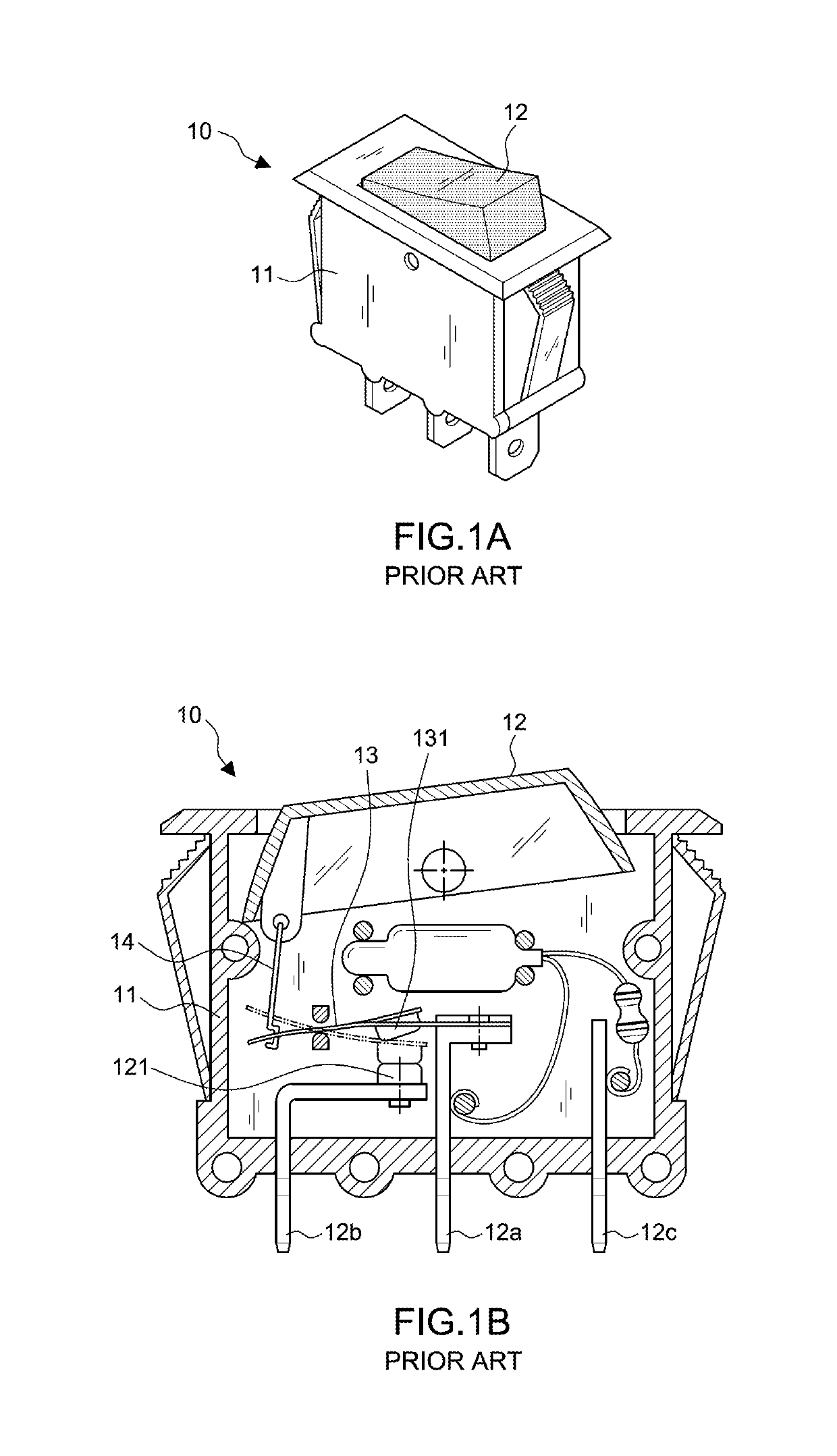
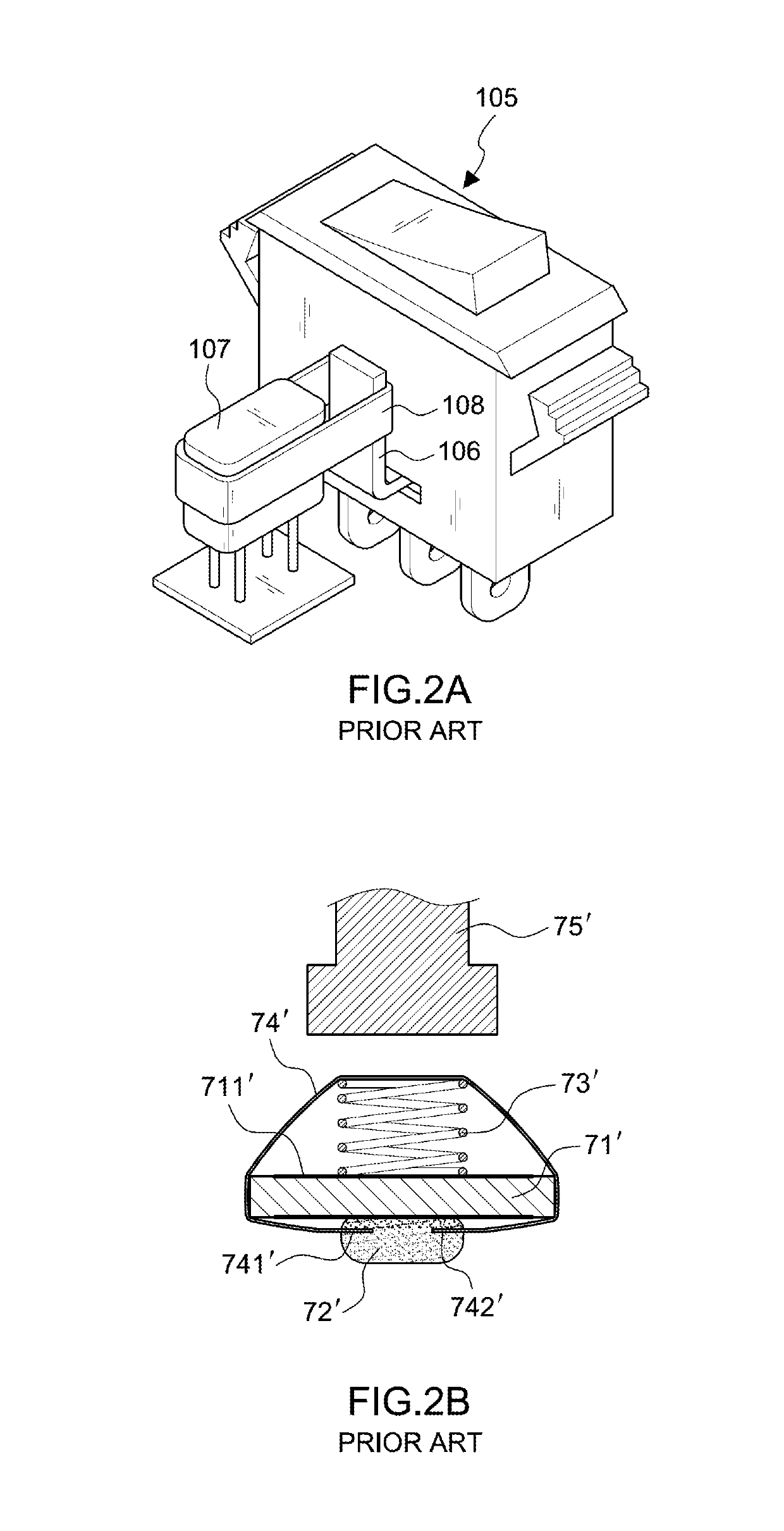
BACKGROUND OF THE INVENTION1. Field of the Invention[0001]The present invention relates to an anti-surge structure that is built in switches and has a plurality of metal-oxide varistors disposed in stair-like arrangement so that each metal-oxide varistor has a surface area for vertically electrical connection, thereby shortening a height of the entire structure.2. Description of the Related Art[0002]FIGS. 1A and 1B disclosed an overcurrent protection switch 10, comprising a housing 11 with a press button 12 on a top thereof, a first terminal 12a, a second terminal 12b, a third terminal 12c at a bottom thereof, and a moving element 14. The first terminal 12a has a bimetal plate 13 and a first contact point 131, and the second terminal 12b has a second contact point 121 corresponding to the first contact point 131. The moving element 14 is arranged vertically, linking a bottom of the press button 12 with an end thereof and a moving terminal of the bimetal plate 13 with another end the...

Claims


Application Information

Patent Timeline
Patent Type & Authority Patents(United States)
IPC IPC(8): H02H1/00H01C10/36H02H9/04H01C7/12
CPCH01C7/12H01C7/126H01C10/36H02H9/041
Inventor WANG, YI-HSIANGWANG, I-YING
Owner WANG YI HSIANG
Learn More