
Antenna transmission device and antenna

a transmission device and antenna technology, applied in the field of mobile communications antennas, can solve the problems of high cost, weight, and size of the antenna transmission mechanism, and achieve the effects of compact structure, high reliability and light weigh

Active Publication Date: 2019-06-11
TONGYU COMM INC
View PDF8 Cites 9 Cited by
  • Summary
  • Abstract
  • Description
  • Claims
  • Application Information

AI Technical Summary

Benefits of technology

The present invention allows for precise control of a single output shaft using a single motor. This design reduces response time, makes the structure more compact, and reduces the weight and cost of the antenna. Additionally, the invention offers the option of forward or reverse rotation to select the desired position and output rotation.

Problems solved by technology

The antenna transmission mechanism has a significant impact on the costs, weight, and size of the antenna.
The costs are high, the weight is heavy, and occupied space is large, and there are disadvantages such as a complex structure, being difficult to produce, and high costs.

Method used


Image

  • Antenna transmission device and antenna
  • Antenna transmission device and antenna
  • Antenna transmission device and antenna

Examples


Embodiment Construction

[0025]To make the objectives, technical solutions, and advantages of the present invention clearer and more comprehensible, the following further describes the present invention in detail with reference to the accompanying drawings and embodiments. It should be understood that the specific embodiments described herein are merely used to explain the present invention but are not intended to limit the protection scope of the present invention.

[0026]The technical solutions in the present invention are described below by using specific embodiments.

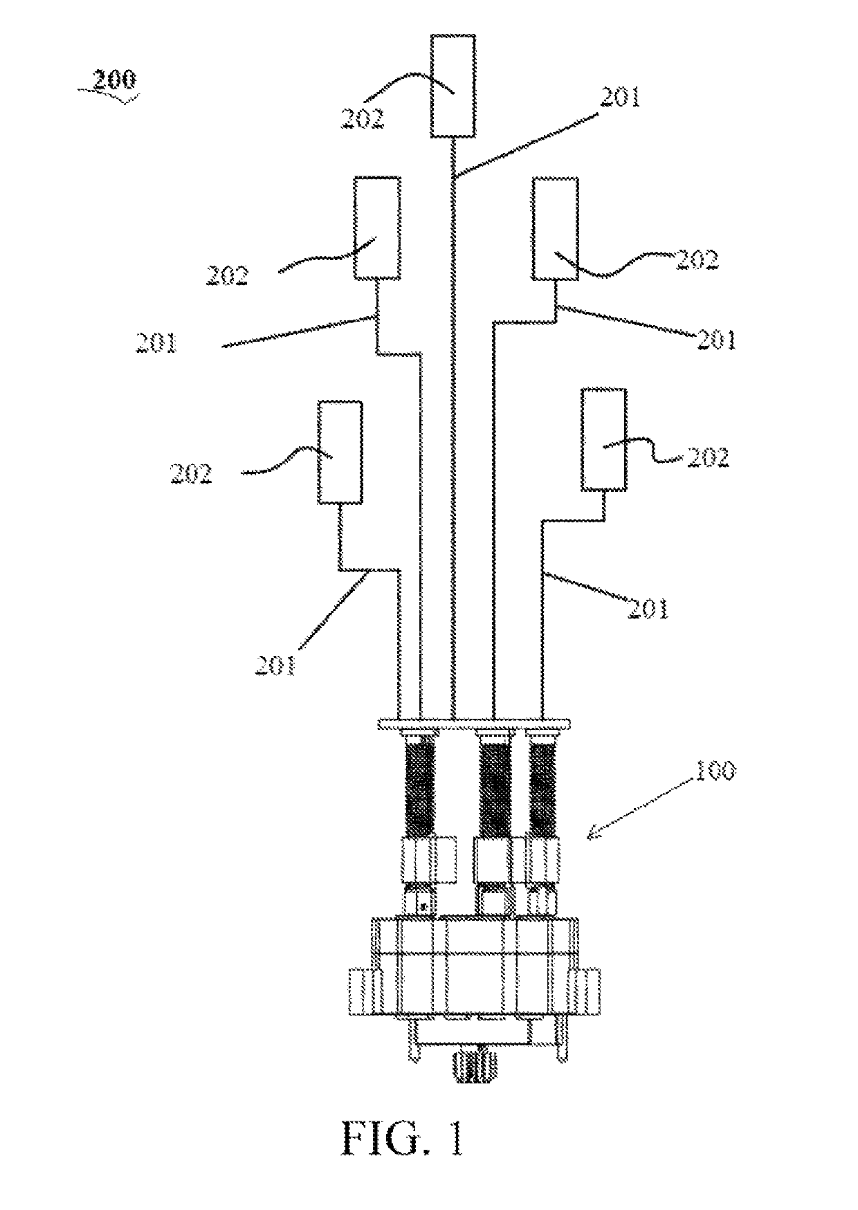
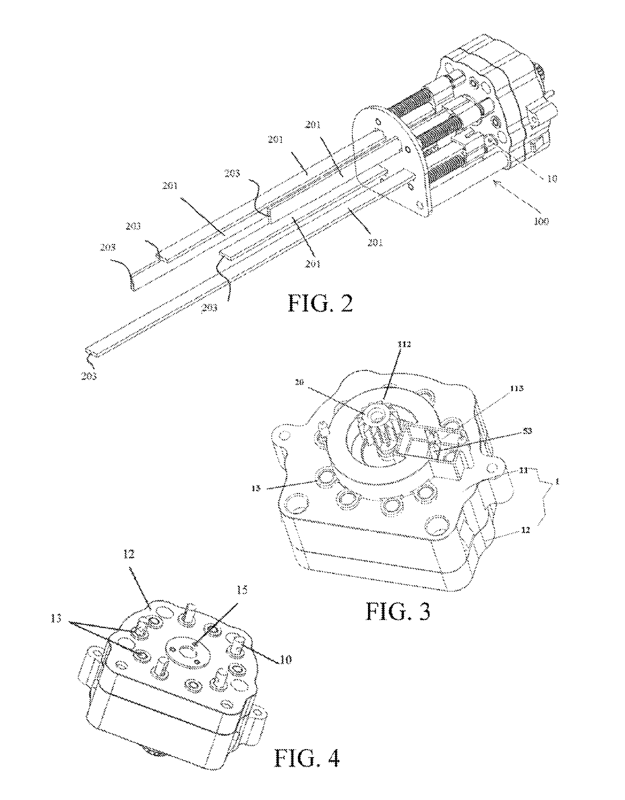
[0027]Referring to FIG. 1 and FIG. 2, a plurality of phase shifters 202 is disposed in a mobile communications antenna 200. To obtain a better radiation characteristic and electrical characteristic, phases of the phase shifters 202 need to be adjusted. Adjustment for the phase shifters is implemented by using an antenna transmission apparatus 100. Each phase shifter 202 is correspondingly connected to an output shaft 10 in the antenna transmis...


PUM


Abstract

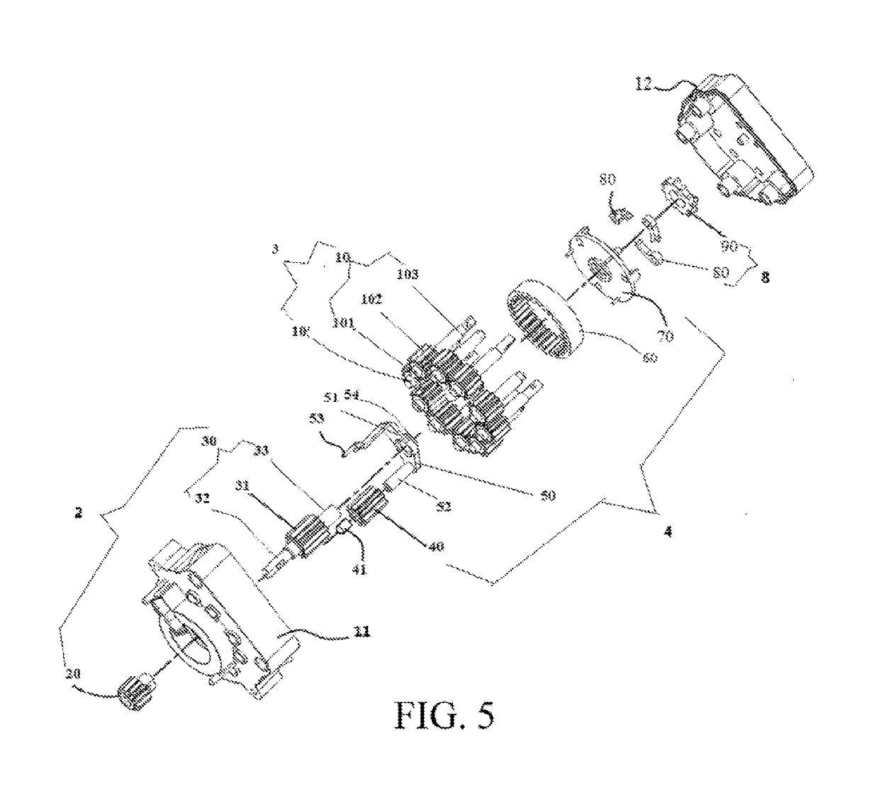
An antenna transmission apparatus includes: a housing including an upper cover and a lower cover, and an input shaft and at least two sets of output shafts that are rotatably mounted between the upper cover and the lower cover; and further includes a planetary gear position selection assembly and a unidirectional control assembly. Each set of output shafts includes an output shaft and an auxiliary shaft in transmission fit with the output shaft; the planetary gear position selection assembly includes a planetary gear; the unidirectional control assembly can control the planetary gear to implement position selection and positioning; and the position selection and bidirectional rotation output of the output shafts may be implemented by using only one motor. The antenna transmission apparatus of the present invention is simple in structure, light in weight, stable, and easy to operate.

Description

BACKGROUNDTechnical Field[0001]The present invention relates to the field of mobile communications antennas, and in particular, to a transmission apparatus for a phase shifter of a base station antenna.Related Art[0002]In mobile communications technologies, a radiation angle of a base station antenna needs to be adjusted to cover different mobile communications areas, and the antenna is generally adjusted by using an antenna transmission mechanism or a remote electrical tilt apparatus. The antenna transmission mechanism has a significant impact on the costs, weight, and size of the antenna. Currently, phase shifters of the base station antennas on the market are mostly one phase shifter driven by one motor. The costs are high, the weight is heavy, and occupied space is large, and there are disadvantages such as a complex structure, being difficult to produce, and high costs.SUMMARY[0003]The technical problem to be resolved in the present invention is to provide an antenna transmissi...

Claims


Application Information

Patent Timeline
Patent Type & Authority Patents(United States)
IPC IPC(8): F16H1/28H01Q1/12F16H1/32H01Q1/24H01Q21/22H01Q3/32F16H31/00
CPCH01Q3/32F16H1/28F16H1/32H01Q21/22H01Q1/1264H01Q1/246F16H31/001F16H1/22F16H3/40
Inventor FANG, TIEYONGWANG, BINCHENG, GANGLIU, MULINHUANG, ZHUOHONGSHI, LEIFANG, ZEMINGYUE, CAILONG
Owner TONGYU COMM INC
Learn More