Supercharge Your Innovation With Domain-Expert AI Agents!

Vehicular control apparatus

a technology of control apparatus and lane change, which is applied in the direction of control devices, external condition input parameters, vehicle components, etc., can solve the problems of difficult to regard lane change as practical, and achieve the effect of suppressing the occurrence of abrupt deceleration

Active Publication Date: 2019-07-02
TOYOTA JIDOSHA KK
View PDF31 Cites 0 Cited by
  • Summary
  • Abstract
  • Description
  • Claims
  • Application Information

AI Technical Summary

Benefits of technology

[0007]In the case where the apparatus described in Japanese Patent Application Publication No. 2003-63273 (JP 2003-63273 A) is improved as described above, the vehicle subjected to automatic speed control runs targeting the first preceding vehicle, so the speed of the vehicle may also be assumed to be higher than that of the second preceding vehicle. In this case, when the vehicle carries out a lane change to the adjacent lane, abrupt deceleration may become necessary to secure an inter-vehicle distance between the vehicle and the second preceding vehicle.
[0008]In the present technical field, it is preferable to suppress the occurrence of abrupt deceleration when a vehicle that is subjected to automatic speed control targeting a preceding vehicle running in front of the vehicle in a driving lane carries out a lane change to an adjacent lane in which there is another preceding vehicle.
[0010]In this vehicular control apparatus, the first target acceleration of the vehicle is calculated based on the speed of the first preceding vehicle running in the driving lane. When the ON signal of the direction indicator is acquired, the second target acceleration of the vehicle is calculated based on the speed of the second preceding vehicle running in the adjacent lane. Then, the smaller of the first target acceleration and the second target acceleration is selected as the target acceleration during the lane change. Therefore, as an example, when the second preceding vehicle running in the adjacent lane is slower than the first preceding vehicle as the target of speed control, the target acceleration during the lane change is set to the second target acceleration based on the second preceding vehicle running in the adjacent lane. Accordingly, the vehicle can start running with reference to the second preceding vehicle at an earlier stage than in the case where the target acceleration during the lane change is identified with the first target acceleration. In consequence, when the vehicle that is subjected to automatic speed control targeting the first preceding vehicle running in front of the vehicle in the driving lane carries out a lane change to the adjacent lane in which the second preceding vehicle exists, the occurrence of abrupt deceleration can be suppressed. Besides, as an example, when the second preceding vehicle running in the adjacent lane is faster than the first preceding vehicle as the target of speed control, the target acceleration during the lane change is set to the first target acceleration based on the first preceding vehicle running in the adjacent lane. Accordingly, an inter-vehicle distance between the vehicle and the first preceding vehicle can be secured during the lane change. As described hitherto, this vehicular control apparatus can restrain the speed of the vehicle from abruptly changing during a lane change.
[0013]By adopting this configuration, when the vehicle that is subjected to automatic speed control targeting the preceding vehicle running in front of the vehicle in the driving lane carries out a lane change to an adjacent lane in which there is another preceding vehicle through automatic steering control, the occurrence of abrupt deceleration can be suppressed.

Problems solved by technology

In the case of a lane change, it is difficult to regard the lane change as practical unless it can be carried out even when there is another vehicle (a second preceding vehicle) in front of and beside the vehicle in an adjacent lane.

Method used


Image

  • Vehicular control apparatus
  • Vehicular control apparatus
  • Vehicular control apparatus

Examples


first embodiment

[0042][Outline of Vehicle]

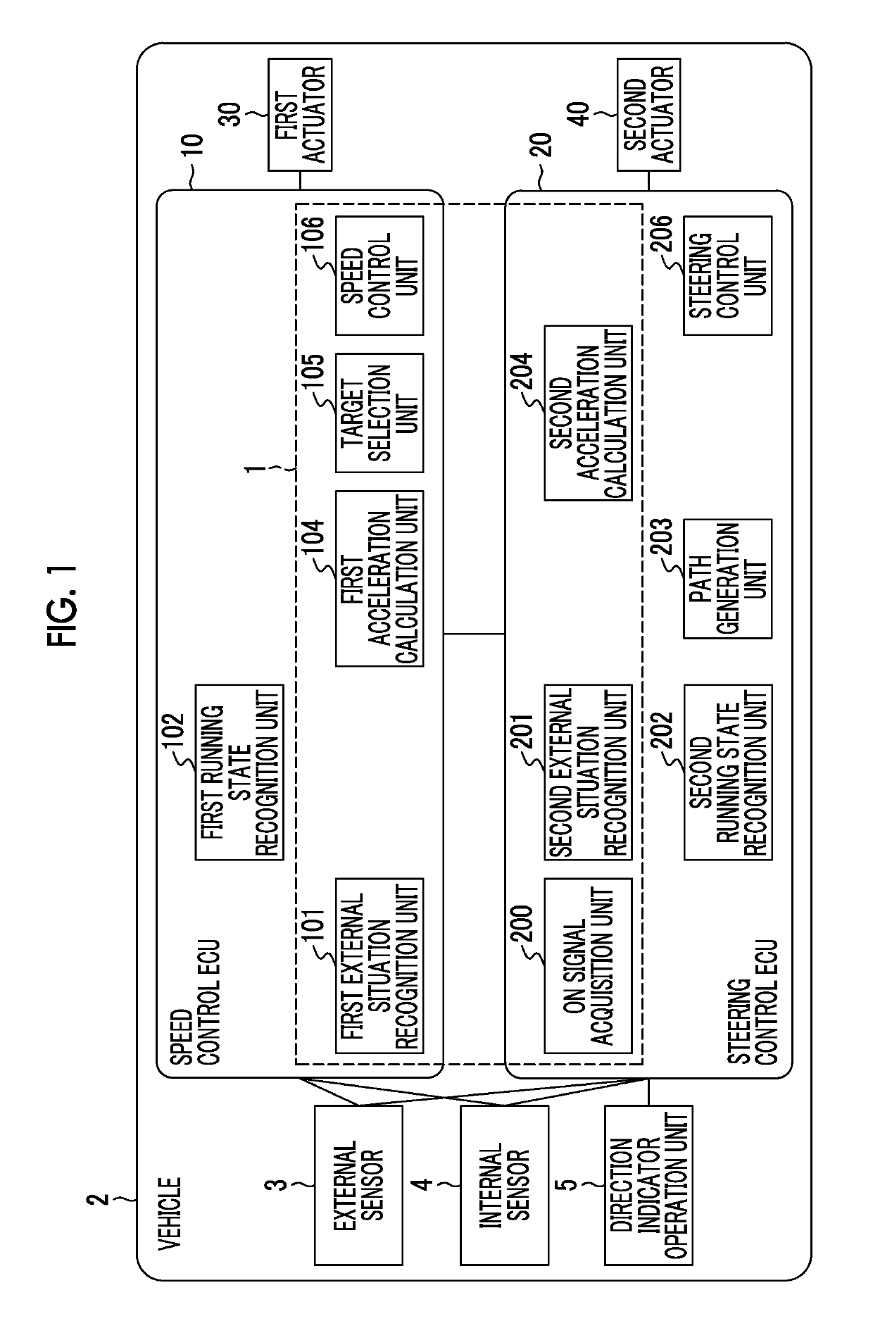
[0043]FIG. 1 is a block diagram illustrating the configuration of a vehicle 2 that is equipped with a vehicular control apparatus 1 according to the first embodiment of the disclosure. As shown in FIG. 1, the vehicular control apparatus 1 is mounted in the vehicle 2 such as a passenger vehicle or the like. As will be described later, the vehicular control apparatus 1 controls the speed of the vehicle 2 during a lane change. A case where the lane change of the vehicle 2 is carried out through automatic steering control will be described hereinafter. That is, the vehicle 2 runs through automatic speed control and automatic steering control.

[0044]The vehicle 2 is equipped with an external sensor 3, an internal sensor 4, a speed control ECU (an electronic control unit) 10, a steering control ECU 20, a first actuator 30 and a second actuator 40. The external sensor 3, the internal sensor 4, the speed control ECU 10, the steering control ECU 20, the first actuato...

second embodiment

[0127]A vehicular control apparatus 1A according to the second embodiment of the disclosure performs automatic speed control of the vehicle 2 in the case where a lane change is carried out manually instead of being carried out through automatic steering control. The vehicular control apparatus 1A according to the second embodiment of the disclosure is different from the vehicular control apparatus 1 according to the first embodiment of the disclosure in that the steering control ECU 20 is not provided and that a speed control ECU 10A is obtained by adding some of the functions of the steering control ECU 20 to the speed control ECU 10. The following description will be given focusing on what is different from the vehicular control apparatus 1 according to the first embodiment of the disclosure, and redundant description will be omitted.

[0128]FIG. 9 is a block diagram illustrating the configuration of a vehicle 2A that is equipped with the vehicular control apparatus 1A according to ...

modification examples

[0135]The speed control ECU 10 and the steering control ECU 20 in the above-mentioned first embodiment of the disclosure do not need to be functionally divided, but may be configured as a single ECU. Alternatively, the functions of the speed control ECU 10 and the steering control ECU 20 may be realized by a plurality of ECU's. Besides, in each of the above-mentioned embodiments of the disclosure, the external sensor 3 is not limited to the LIDAR, but may be a radar that outputs microwaves or the like. Besides, the vehicle 2 may be equipped with a LIDAR as the external sensor 3, a camera and a LIDAR at the same time.

[0136]In each of the above-mentioned embodiments of the disclosure, when the vehicle is equipped with a regenerative brake system, the brake actuator may control both the hydraulic brake system and the regenerative brake system.

[0137]In each of the above-mentioned embodiments of the disclosure, the example in which the first acceleration calculation unit 104 calculates t...


PUM


Abstract

A vehicular control apparatus includes at least one electronic control unit. The at least one electronic control unit is configured to recognize a first preceding vehicle in a driving lane and to calculate a first target acceleration of the vehicle. The at least one electronic control unit is also configured to recognize a second preceding vehicle in an adjacent lane, and to calculate a second target acceleration of the vehicle. The at least one electronic control unit is configured to acquire lane change information of the vehicle, and to select the smaller of the first target acceleration and the second target acceleration as a target acceleration of the vehicle. The at least one electronic control unit is configured to control a speed of the vehicle in a lane change period by using the selected target acceleration.

Description

INCORPORATION BY REFERENCE[0001]The disclosure of Japanese Patent Application No. 2015-254481 filed on Dec. 25, 2015 including the specification, drawings and abstract is incorporated herein by reference in its entirety.BACKGROUND[0002]1. Technical Field[0003]The present disclosure relates to a vehicular control apparatus.[0004]2. Description of Related Art[0005]In Japanese Patent Application Publication No. 2003-63273 (JP 2003-63273 A), there is described a control apparatus that realizes overtaking through automatic driving during automatic speed control. The control apparatus targets a preceding vehicle (a first preceding vehicle) running in front of a vehicle in a driving lane, and causes the vehicle to follow this preceding vehicle. The control apparatus determines whether or not there is another vehicle behind and beside the vehicle in an adjacent lane in overtaking the first preceding vehicle. Then, the control apparatus stops the vehicle from overtaking the first preceding v...

Claims


Application Information

Patent Timeline
Patent Type & Authority Patents(United States)
IPC IPC(8): B60W30/18
CPCB60W30/18163B60W2550/30B60W30/16B60W2720/106B60W2554/4041B60W2554/804B60W2554/80B60W2554/801B60W2554/802
Inventor MATSUMOTO, KENTAROASO, KAZUAKIMORIMURA, JUNICHI
Owner TOYOTA JIDOSHA KK
Features
  • R&D
  • Intellectual Property
  • Life Sciences
  • Materials
  • Tech Scout
  • Unparalleled Data Quality
  • Higher Quality Content
  • 60% Fewer Hallucinations
Learn More