
Method for improved aerial lighting

Active Publication Date: 2019-07-02
MUSCO
View PDF10 Cites 6 Cited by
  • Summary
  • Abstract
  • Description
  • Claims
  • Application Information

AI Technical Summary

Benefits of technology

The patent text describes a method for controlling lighting to improve playability and enhance the view of the field for sports. This is achieved by using lighting arrays with directed light sources that create shadow or glare for players in certain positions. The method also includes identifying participants and critical or important directions of sight, and directing the lighting to provide optimal visibility for the game play while reducing glare for the participants. The overall effect is an improved and unobstructed view of the game for players and spectators.

Problems solved by technology

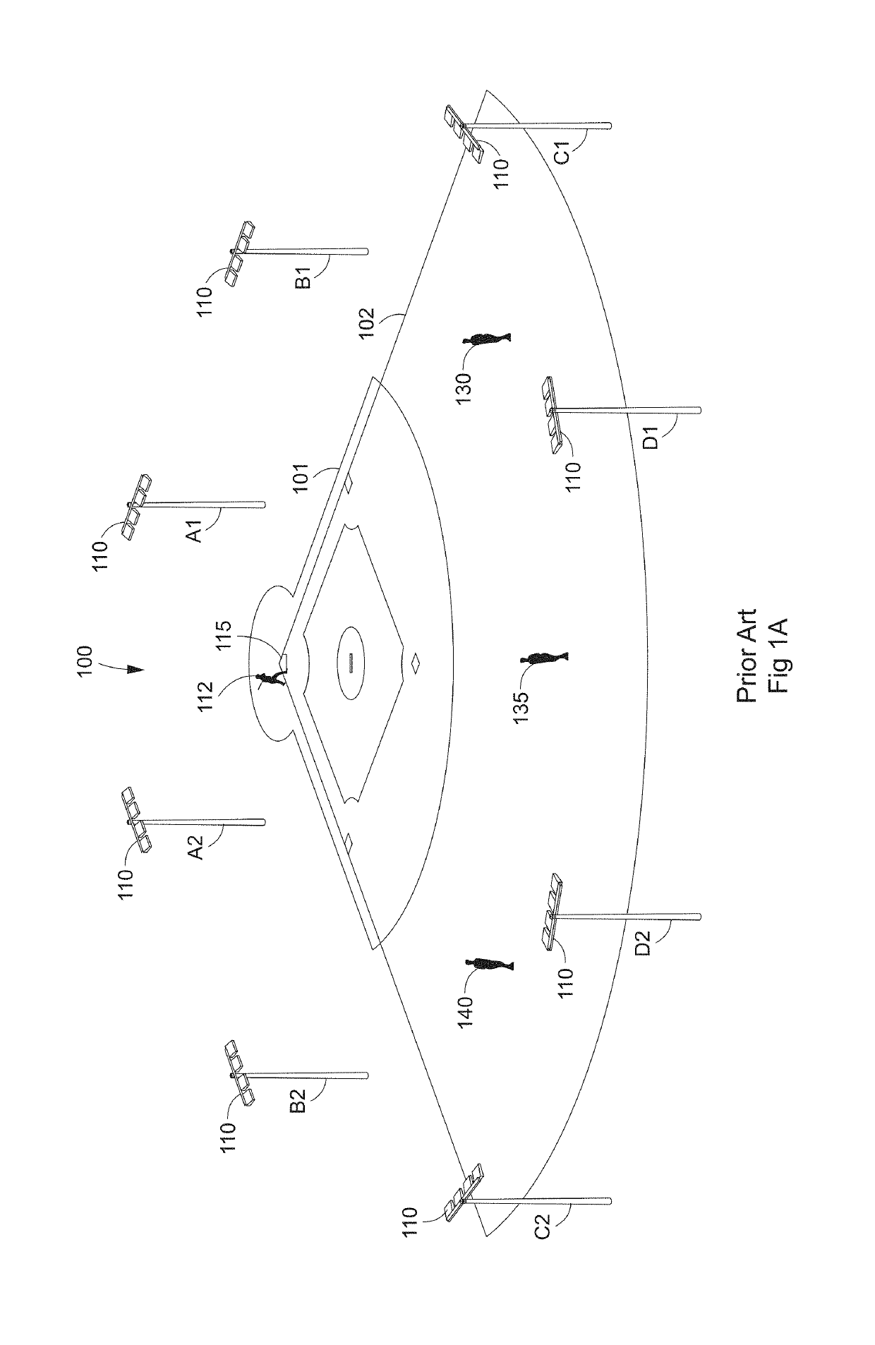
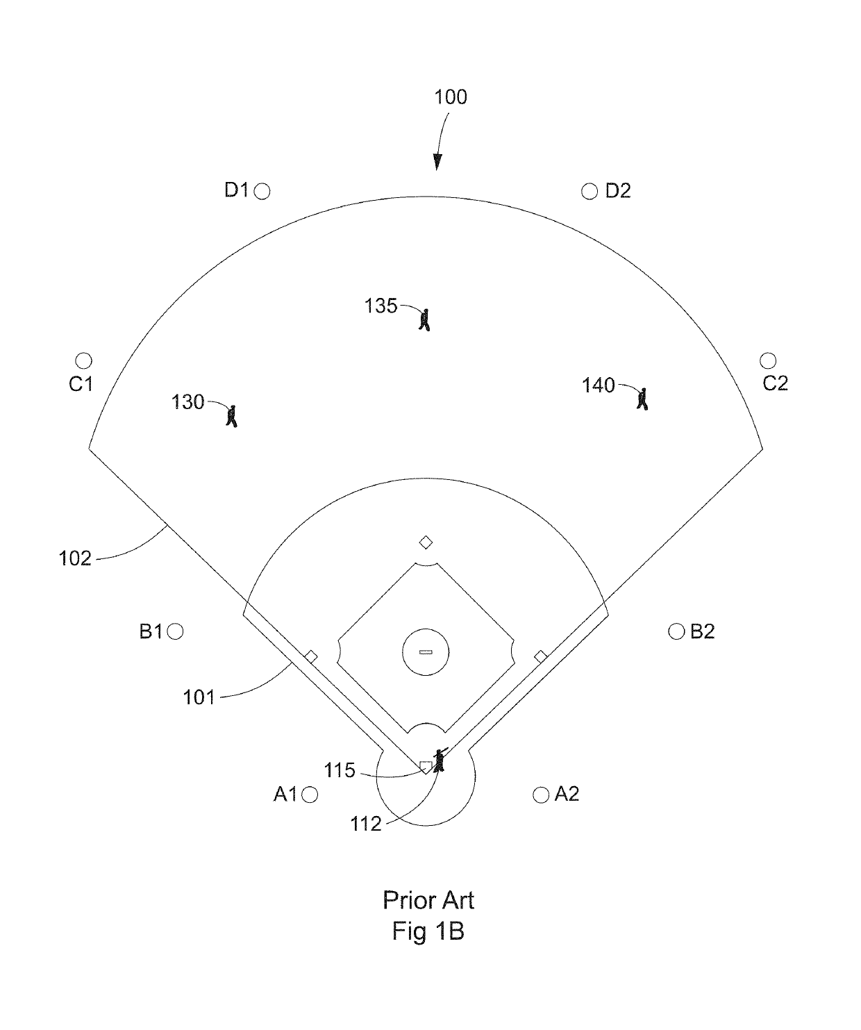
Various methods to improve aerial lighting have been proposed over the years, including providing uplighting by using low-mounted uplights on existing poles; however, some venues (such as e.g. major league and minor league baseball fields), typically mount lights on support structures above or behind spectator seating and do not allow the use of lighting poles or other mounting structures which are between spectators and the playing field such as would be required for low-mounted uplights.
This precludes the use of low-mounted uplights for these venues and therefore requires a different approach to reducing glare for certain players and situations.
Also, low-mounted uplights may not be desired for aesthetic or practical reasons.

Method used


Image

  • Method for improved aerial lighting
  • Method for improved aerial lighting
  • Method for improved aerial lighting

Examples


exemplary embodiment 1

D. Reducing Glare

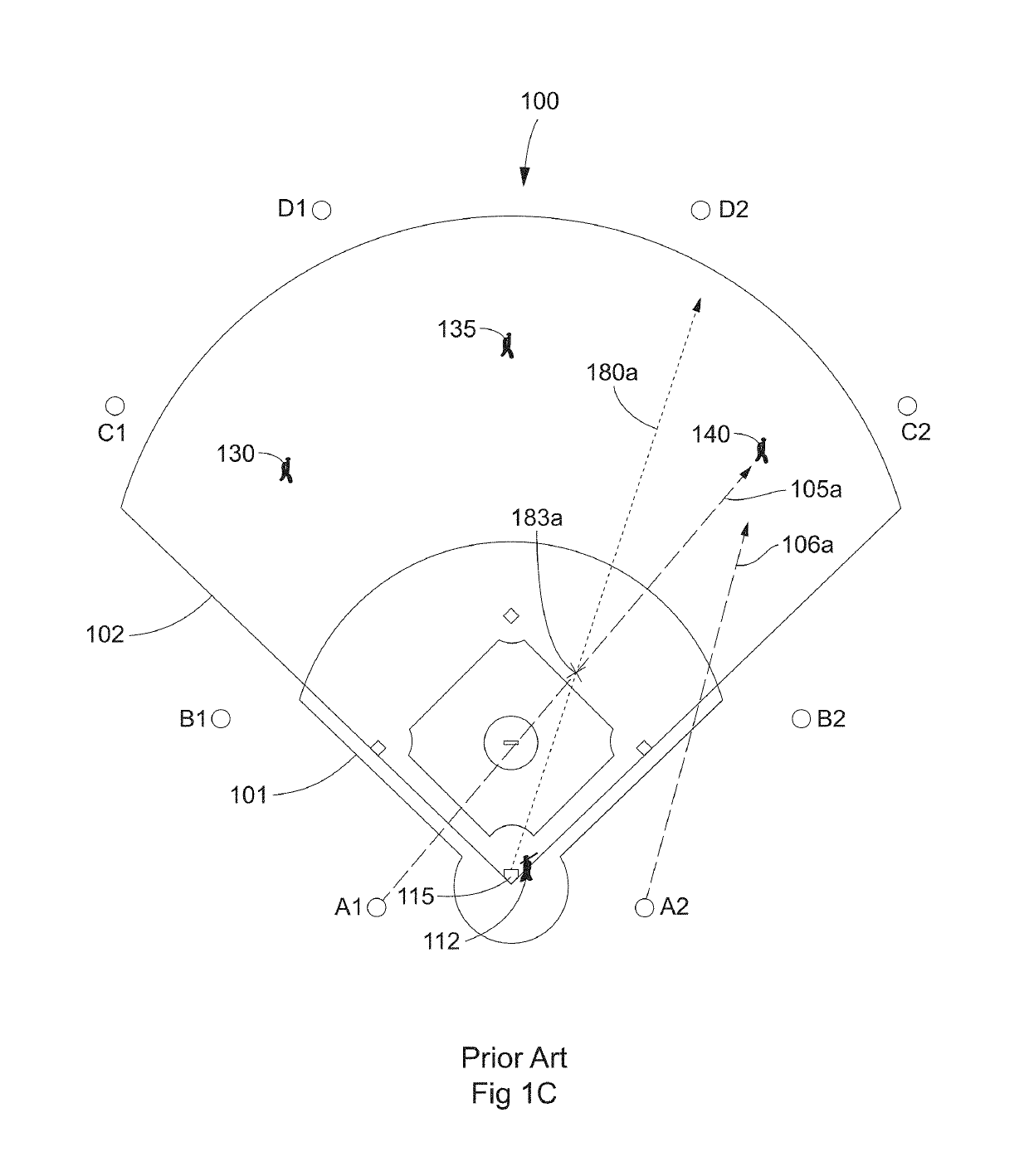
[0049]FIG. 5 illustrates a flow chart describing a method 500 according to aspects of the invention for reducing glare for players. According to step 501, a player position such as e.g. left fielder 130 (FIG. 2B) is analyzed for potential glare based on the activity of the player with regard to potential glare sources which could include e.g. poles A1, A2, B1, and B2 (FIG. 1C). In step 502, an identified potential source of glare such as pole A2 has its aiming, visoring, or other factors modified to eliminate glare by shielding the player from direct view of the light source. In step 503, the lighting distribution for ground and aerial spaces (such as shown for example in aiming diagram 602, FIG. 6 for baseball field 100 and in diagram 30C, FIG. 7 for uplight, respectively) is checked to determine if adequate lighting remains from other sources at other angles which are less likely to cause glare. If necessary, in step 504 lighting sources such as e.g. at poles A1 a...


PUM


Abstract

Discussed herein is a new way to light baseball fields or other target areas (e.g., target areas including a plane and an aerial space) according to accepted standards or desired levels which provides both target area lighting and uplighting and in a manner that reduces or eliminates glare for certain playing positions while maintaining lighting levels across both the target area and the aerial space above the target area without necessitating the use of low-mounted uplights.

Description

CROSS-REFERENCE TO RELATED APPLICATIONS[0001]This application claims priority under 35 U.S.C. § 119 to provisional U.S. Application Ser. No. 62 / 409,622, filed Oct. 18, 2016, hereby incorporated by reference in its entirety.I. TECHNICAL FIELD OF INVENTION[0002]The present invention generally relates to lighting of a target area, and issues that arise when the target area includes an aerial space. In the current state of the art, lighting for the aerial space sometimes must be provided from luminaire locations and aiming angles that can cause perceived glare by certain players who look directly or nearly directly into the light sources during play. In an effort to reduce perception of glare, aerial lighting intensity may be reduced, possibly to a point of being inadequate. Also, or instead, luminaires may be installed for aerial lighting in locations that are disadvantageous or create additional costs. The present invention specifically relates to providing improved aerial lighting wi...

Claims


Application Information

Patent Timeline
IPC IPC(8): H05B37/02F21V21/116F21S2/00F21S8/08F21V7/09F21W131/105F21W131/40
CPCF21S8/081F21V21/116F21S2/00F21V7/09F21W2131/105A63C2203/14F21W2131/40F21S8/08
Inventor GORDIN, MYRON
Owner MUSCO
Learn More