
Directed energy weapon

a directed energy and weapon technology, applied in the direction of weapons, lasers, basic electric elements, etc., can solve the problems of insufficient output power of single fiber laser using current technology, and the problem of high energy beam suitable lasers, etc., to achieve optimal directed energy weapons. the effect of output power

Active Publication Date: 2019-07-02
RAFAEL ADVANCED DEFENSE SYSTEMS
View PDF3 Cites 3 Cited by
  • Summary
  • Abstract
  • Description
  • Claims
  • Application Information

AI Technical Summary

Problems solved by technology

Various types of lasers suitable for generating high energy beams are problematic for practical implementations of a weapon due to their reliance on dangerous chemicals or requirements for bulky hardware.
Although output powers of more than 1 kW are available, output from a single fiber laser using current technology does not provide sufficient output power for implementation of an optimal directed energy weapon.

Method used


Image

  • Directed energy weapon
  • Directed energy weapon
  • Directed energy weapon

Examples


Embodiment Construction

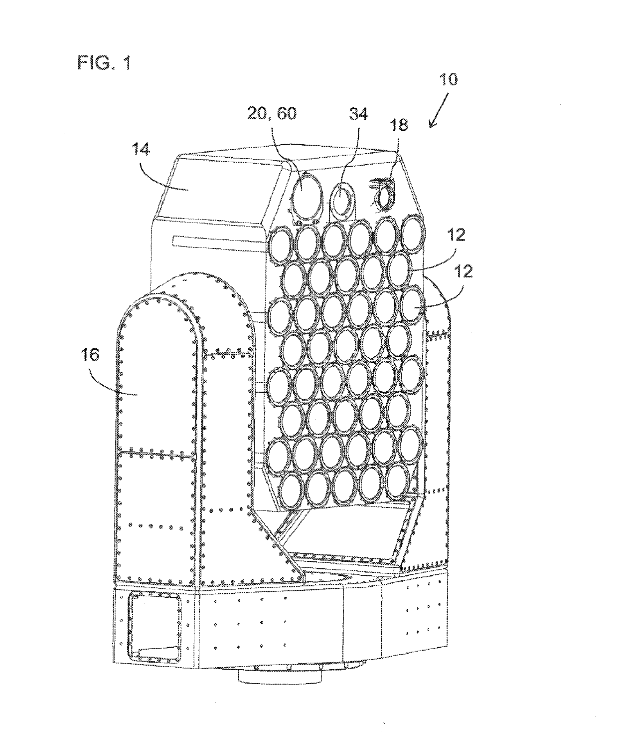
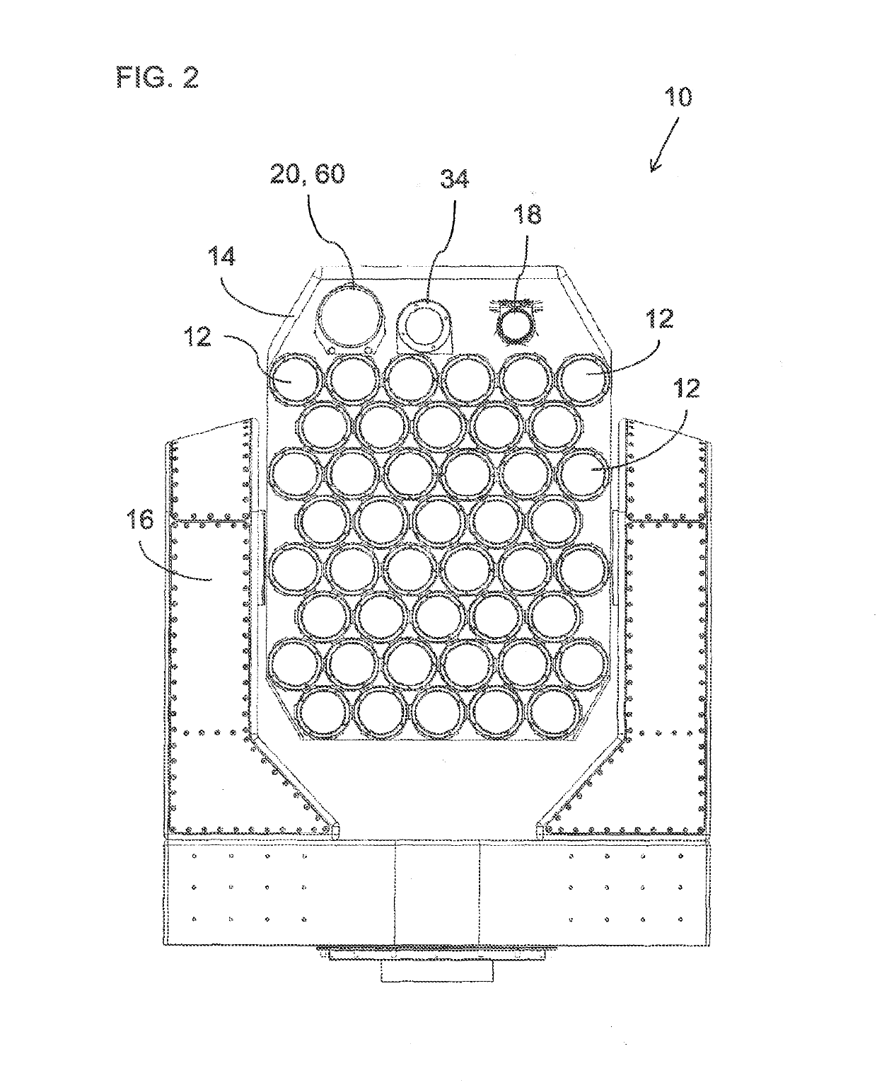
[0039]The present invention is a directed energy weapon based on fiber lasers.

[0040]The principles and operation of directed energy weapons according to the present invention may be better understood with reference to the drawings and the accompanying description.

[0041]By way of introduction, the present invention has a number of distinct aspects, each of which is believed to be worthy of patent protection in its own right, and which are believed to be of particular significance when employed together in synergy. Specifically, a first aspect of the present invention relates to a system and corresponding method for ensuring correct relative inter-beam alignment (IBA) between multiple beams from separate fiber laser units, each with its own objective optics. This inter-beam alignment facilitates reliable tracking of multiple fiber laser units on a common target while using a shared fine alignment tracker. A second aspect of the present invention relates to a compact autonomous trackin...


PUM


Abstract

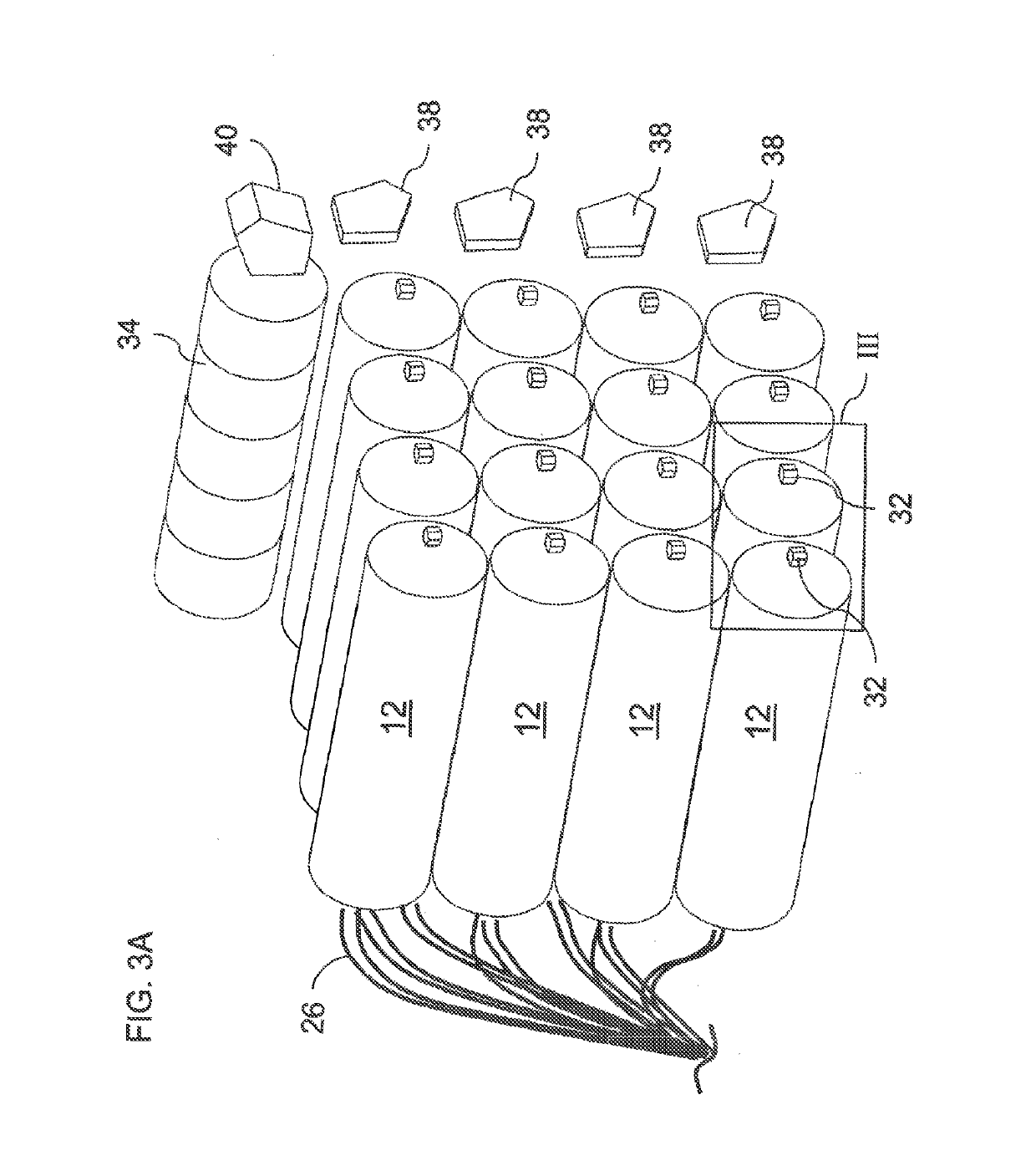
A directed energy weapon includes a number of laser units, each including a fiber laser generating an output beam with a power of at least 1 kW from a fiber, an objective lens arrangement for focusing the output beam into a focused beam directed towards a target, and a fine adjustment mechanism for adjusting a direction of the focused beam. A beam deflector arrangement is deployed to deflect a portion of the focused beam from each laser unit as a deflected beam in a direction in predefined relation to a direction of the focused beam. An angle sensing unit generates an output indicative of a current direction of said deflected beam for each of said laser units. A controller actuates the fine adjustment mechanisms based on the output from the angle sensing unit to maintain a desired relative alignment between directions of the focused beams.

Description

FIELD AND BACKGROUND OF THE INVENTION[0001]The present invention relates to directed energy weapons and, in particular, it concerns directed energy weapons based on fiber lasers.[0002]It has been proposed to use high energy laser (HEL) radiation focused on a target as weapon, both in offensive and defensive roles. Various types of lasers suitable for generating high energy beams are problematic for practical implementations of a weapon due to their reliance on dangerous chemicals or requirements for bulky hardware.[0003]Fiber lasers, i.e., lasers in which the active gain occurs within an optical fiber, are compact and avoid use of dangerous chemicals. Although output powers of more than 1 kW are available, output from a single fiber laser using current technology does not provide sufficient output power for implementation of an optimal directed energy weapon.[0004]Various attempts have been made to combine multiple fiber lasers in a directed energy weapon so as to provide a desired ...

Claims


Application Information

Patent Timeline
Patent Type & Authority Patents(United States)
IPC IPC(8): H01S3/00F41H13/00H01S3/067H01S3/23
CPCF41H13/0062H01S3/0071H01S3/2383H01S3/067H01S3/005F41H5/20
Inventor SEGEV, YEHONATANSWIRSKI, YOCHAYYOSUB, SHAYITOVICH, YAN
Owner RAFAEL ADVANCED DEFENSE SYSTEMS
Learn More