Modular fuel cell structure, casing of the same, and fuel cell system

a fuel cell and modular technology, applied in the field of fuel cells, can solve the problems of increasing the heat island effect in metropolitan areas, the impact of high oil prices, and the end of cheap petrochemical energy, and achieve the effect of eliminating

Active Publication Date: 2019-07-02
NAT TAIPEI UNIV OF TECH
View PDF9 Cites 0 Cited by
  • Summary
  • Abstract
  • Description
  • Claims
  • Application Information

AI Technical Summary

Benefits of technology

[0017]In view of the above, the primary objective of the present invention is to provide a modular fuel cell structure, a casing of the modular fuel cell structure, and a fuel cell system. Through the innovative fuel filling mechanism, and the optimization of the battery structure, the fuel applied in the battery could be fully reacted, and could be effectively removed afterwards.
[0021]By separately injecting the first material and the second material from the first and second flow passages in the modular fuel cell structure, the proportion of the materials injected into the reaction vessel could be ensured, so that the first material and the second material could be sufficient reacted, whereby to make the fuel cell reaction more homogeneous and stable.

Problems solved by technology

However, the cheap petrochemical energy will eventually dry up, and the world is bound to face the impact of high oil prices caused by the reduction of petrochemical capacity in the future.
How to reduce the reliance on fossil fuels and appropriately use limited energy has become one of the important issues in energy policy for the whole world.
Besides that, the heat island effect in metropolitan areas will become increasingly severe along with the development of megacities, and microscopic particles suspended in the air (e.g., PM 2.5) will also directly affect human health.
Therefore, after the World Wide Views on Climate and Energy, how to provide high-performance, low-pollution energy in metropolitan areas will be an urgent and important issue for every country in pursuit of sustainable development.
As a result, the battery performance gradually reduces as well.
Furthermore, the zinc anode plate of battery has to be replaced in mechanical ways after the reaction is completed, which is very inconvenient.
On the other hand, the development of secondary zinc-air batteries is still in a bottleneck, and therefore are not widely used in personal medical aids and energy systems yet.
1. Air cathode has poor discharge power.
2. Isolation membrane has poor ionic conductivity.
3. Zinc anode cannot operate for a long time.
4. Zinc particles cannot be fully utilized as fuel.
5. The interrelated relationship between air, water and heat management system, and voltage monitoring technology still has to be integrated.
However, with such design for battery structure, the injected fuel may not be evenly mixed, causing low performance for fuel cells.
In other words, the ratio of metal particles to an electrolytic solution for the electrochemical reaction is difficult to manipulate as appropriate, for the injected electrolytic solution which contains metal particles may be mixed unevenly.
As a result, there might be no sufficient metal particles in a fuel cell for reaction, leading to poor efficiency.
Thus, conventional fuel cells still have many challenges to be overcome.

Method used


Image

  • Modular fuel cell structure, casing of the same, and fuel cell system
  • Modular fuel cell structure, casing of the same, and fuel cell system
  • Modular fuel cell structure, casing of the same, and fuel cell system

Examples


Embodiment Construction

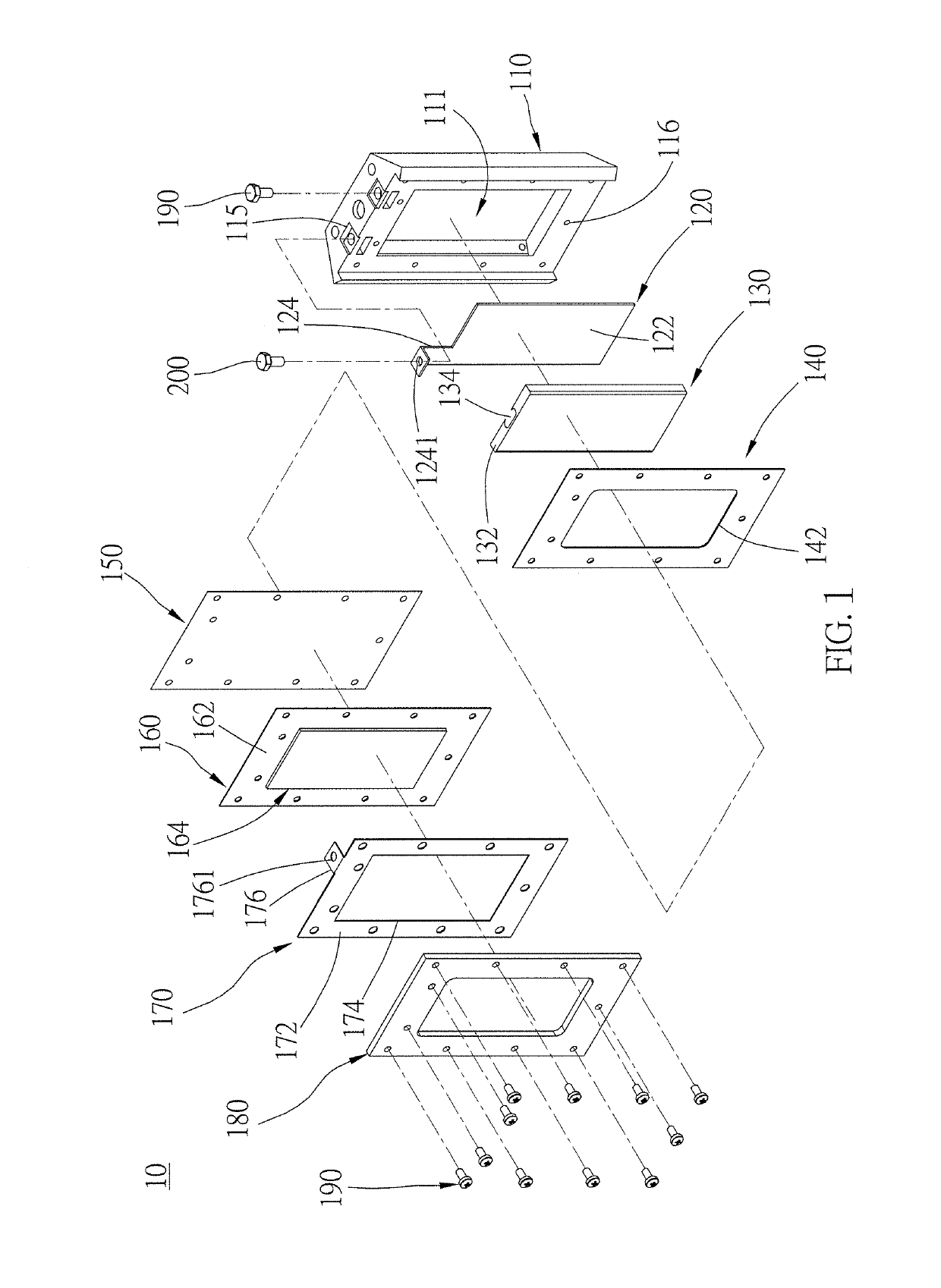
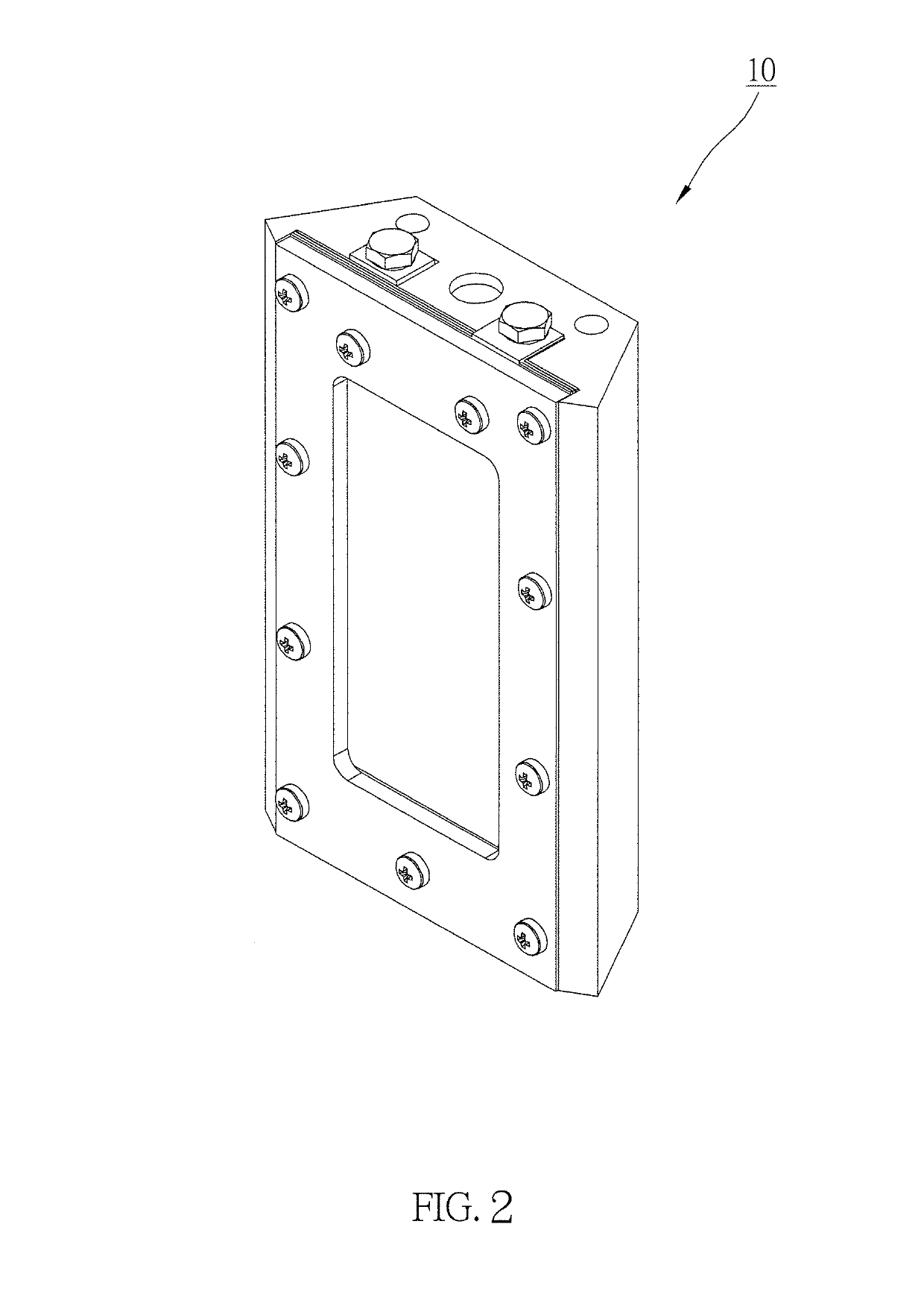
[0030]As shown in FIG. 1 and FIG. 2, a modular fuel cell structure 10 of an embodiment of the present invention is adapted to inject a first material and a second material, so that the first material and the second material could be mixed in the modular fuel cell structure 10 for reaction, whereby to generate and output electrical power. Therefore, the first material and the second material are fuels for power generation, wherein the first material could be an electrolyte solution, while the second material could be metal particles. For example, the first material is potassium hydroxide electrolyte, and the second material is zinc particles. However, the exemplified materials are not limitations of the present invention.

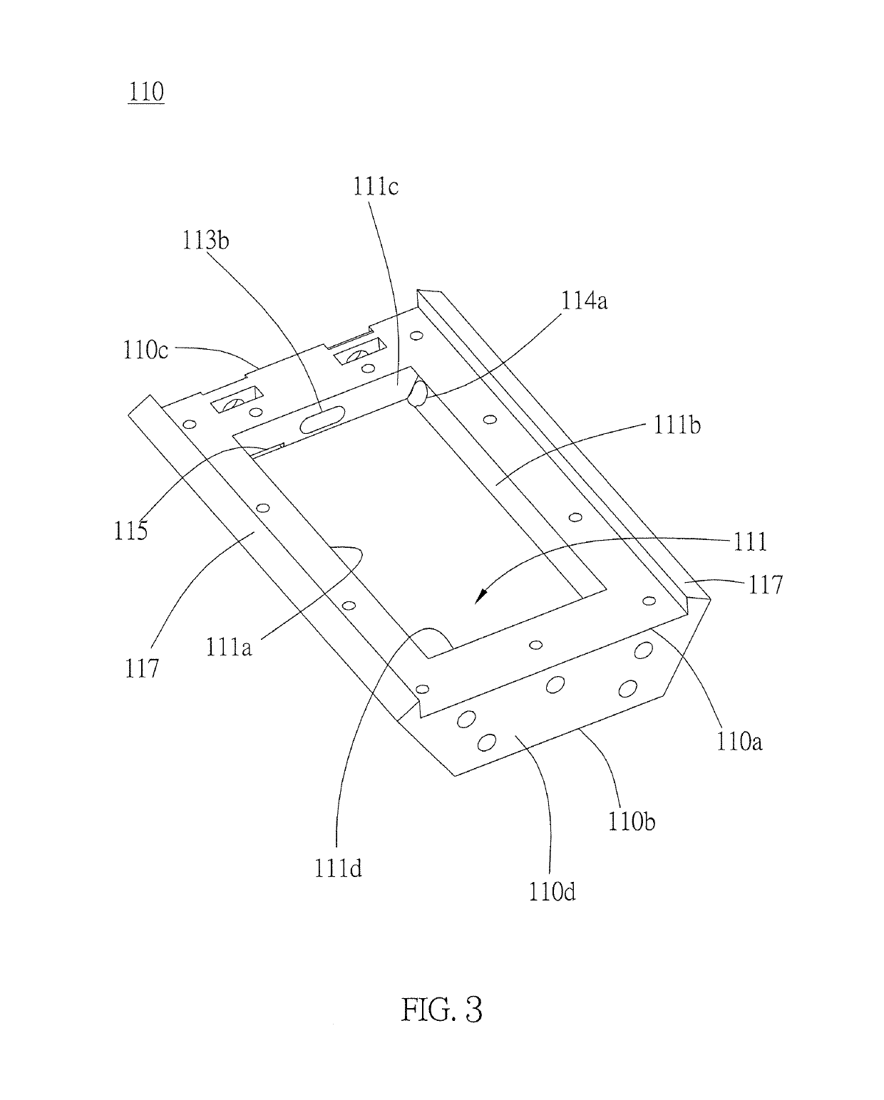
[0031]The modular fuel cell structure 10 includes a casing 110, an anode conductive sheet 120, an anode conductive grid 130, a liner 140, a separating membrane 150, an air electrode sheet 160, a cathode conductive sheet 170, and a cover plate 180.

[0032]As shown in FI...


PUM

PropertyMeasurementUnit
included angleaaaaaaaaaa
degree of freedomaaaaaaaaaa
conductiveaaaaaaaaaa

Abstract

A modular fuel cell structure includes an anode conductive sheet, an air electrode sheet, a separating membrane, and a cathode conductive sheet stacked on a casing. The casing has a reaction vessel, and also has a first, a second, and a third flow passages, which all communicates with the reaction vessel, and are all independent. Said modular structure forms a fuel cell system with a first storage tank, a second storage tank, a retrieval device, and a feeding device which controls the first and the second storage tanks to deliver a first and a second materials to the casing. The first and the second materials are respectively injected into the reaction vessel for reaction through the first and the second flow passages, and then exhausted to the retrieval device through the third flow passage after the reaction. With the independent flow passages, the efficiency of power generation could be improved.

Description

BACKGROUND OF THE INVENTION[0001]1. Technical Field[0002]The present invention relates generally to fuel cell, and more particularly to a modular fuel cell structure, a casing of the modular fuel cell structure, and a fuel cell system.[0003]2. Description of Related Art[0004]After the industrial revolution in the nineteenth century, fossil fuels have become the main energy source. In addition to providing a vast amount of energy for humanity, an enormous amount of plastic products is also manufactured by using the abundant oil, coal, and natural gas on the planet. However, the cheap petrochemical energy will eventually dry up, and the world is bound to face the impact of high oil prices caused by the reduction of petrochemical capacity in the future. How to reduce the reliance on fossil fuels and appropriately use limited energy has become one of the important issues in energy policy for the whole world.[0005]In addition to energy and economic issues, environmental issues have also ...

Claims


Application Information

Patent Timeline
Patent Type & Authority Patents(United States)
IPC IPC(8): H01M12/06H01M8/18H01M8/04082H01M8/04276H01M8/22H01M12/08
CPCH01M8/04201H01M8/04276H01M8/188H01M12/06H01M12/065H01M12/08H01M8/225Y02E60/128Y02E60/50Y02E60/10
Inventor HUANG, KUOHSIU DAVIDHSU, TING-WEI
Owner NAT TAIPEI UNIV OF TECH
Why Eureka
Try Eureka