Removable storage module mounting system for golf cart

a golf cart and storage module technology, applied in the direction of golf club bags, transportation and packaging, sports equipment, etc., can solve the problems of little or no security for items being transported, storage area not protected from inclement weather, and little flexibility in storage, so as to facilitate and reduce the cost of shipping the unit, the effect of less storage spa

Inactive Publication Date: 2019-07-09
BONENBERGER FR PHILIP
View PDF8 Cites 3 Cited by
  • Summary
  • Abstract
  • Description
  • Claims
  • Application Information

AI Technical Summary

Benefits of technology

[0023]The invention described herein relates generally to a golf cart mounted storage unit, and solves these and other problems as described below. Features of this invention should include the ability to protect items being transported from rain, theft and temperature extremes. It should allow some reconfiguration to accommodate different sizes, shapes and types of items. In addition, it would be desirable to have this storage unit be removable from the golf cart, so that the cart could be used for its original purpose of transporting golf clubs, and ideally the unit should be collapsible so that it would require less storage space when not in use on the cart. This would also allow for easier and cheaper shipping of the unit. This invention provides these advantages.
[0027]Another embodiment of this invention has this storage unit built out of lightweight materials, so that it can be easily removed from the golf cart if it is desirable to use said cart for golfing. This is also desirable for shipping or otherwise transporting said storage unit, whether before or after it is assembled. In a preferred embodiment, this storage unit will be removably attached to the back of the golf cart.

Problems solved by technology

Since a golf cart is normally used only for golfing in good weather, storage areas are not protected from inclement weather such as rain or temperature extremes.
Since it is also normally attended by the golfers for the full time it is on the course, the storage provides little or no security for items being transported.
Finally, there is little flexibility in storage, as its primary storage area is configured to hold nothing more or less than two bags of golf clubs.

Method used


Image

  • Removable storage module mounting system for golf cart
  • Removable storage module mounting system for golf cart
  • Removable storage module mounting system for golf cart

Examples


first embodiment

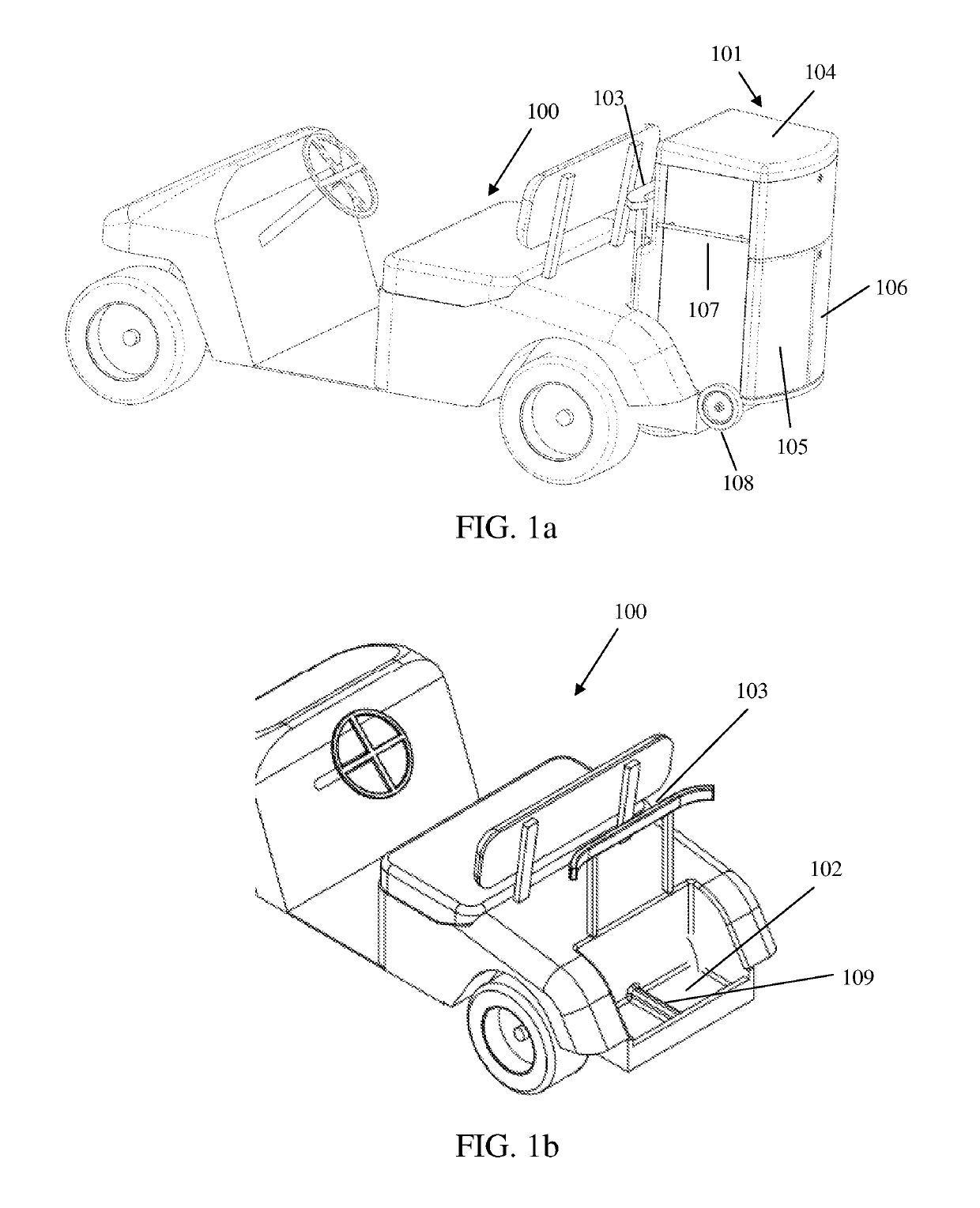
[0039]the storage unit shown has a top door 104, which opens upward, and two front doors 105 and 106. It also has a handle 107 and another on the far side (not shown) to lift the storage unit from the back of the golf cart, and a wheel 108 paired with another wheel on the far side (not shown) to roll the storage unit around when it is separated from the golf cart. These wheels may be removably attached or folded up out of the way when the storage unit is being used on the back of a vehicle. As shown, they are designed to extend below the bottom horizontal plane of the bottom panel of the storage unit when deployed so that the storage unit can be rolled.

[0040]The storage unit is designed to be of lightweight construction and thus easily removable. In a preferred embodiment, the construction is largely of plastic such as, but not limited to, polycarbonate, polystyrene, PVC (poly vinyl chloride), HDPE (high density polyethylene), and PE (polyethylene). In another embodiment, the constr...

second embodiment

[0047]FIG. 2e shows a rear view of the storage unit, with a section of the golf cart frame cross brace 223 and a vertical plate 224 for an upper attachment point, to be discussed in more detail later. On the sides of the storage unit are shown handles 225 and 226, to help remove the storage unit from the golf cart platform. Below the bottom of the box is another embodiment of an adjustable bottom protrusion. In this embodiment, in addition to the two side leg / plate combinations 227 and 228 with extendable side arms 229 and 230 seen in the previous embodiment, we also see a center extendable arm 231, and a kick stand 232, with a dotted line showing the arc of its swing. This kick stand would allow the storage unit to stand level on its front wheels and kick stand when it is not mounted on the golf cart rear shelf.

[0048]FIG. 2f shows a bottom view of the second embodiment of an adjustable bottom protrusion. Center extendable arms 233 and 234 slide into holder 235, which is attached to...

third embodiment

[0050]FIG. 2h shows a bottom view of the third embodiment, with bottom plates and extendable arms similar to those shown in FIG. 2d. The kick stand 240 shown here is U-shaped, with two pivot points 248 and 249. The pivot points could be moved elsewhere, clearly, depending on the configuration of the access panel, bottom plates and adjustable arms. Also note that in other embodiments not shown in figures a second set of wheels could be used in addition to 214, shown, which could fold out or attach, rather than a kick stand, in order to hold the storage unit level. This would have the disadvantage of greater expense and complexity, but the advantage of being able to wheel the storage unit around without having to tilt it onto two wheels, making it easier to move for someone with strength or mobility impairments.


PUM


Abstract

A storage unit intended for mounting on the rear of a golf cart type vehicle is designed to protrude from the rear of the golf cart to provide more storage space. The storage unit is further designed to be removable, and may be subdivided with movable partitions. Several features are described for its attachment onto the rear of the golf cart in different ways, including specific types of attachments and frameworks for use with and without rear shelf wells on the golf cart. These are designed for greater security in holding the storage unit onto the golf cart, and include adjustable or removable bottom protrusions for use with a rear shelf well, or the attachment frame system without a rear shelf well. In addition, a system is described to allow the storage unit to be folded, such that it can be more compactly folded and shipped, stored or transported.

Description

CROSS REFERENCE TO RELATED APPLICATIONS[0001]This application is a Continuation in Part of Utility application Ser. No. 14 / 167,922, filed Jan. 29, 2014, which takes its priority from Provisional Application 61 / 760,016, filed Feb. 1, 2013, both of which are incorporated by reference. This application also takes priority from Provisional Application 62 / 394,729, filed Sep. 14, 2016, which is incorporated by reference. As per the requirements of 1.78(6), the inventors hereby state that this nonprovisional application which is being filed on or after Mar. 16, 2013, claims the benefit of the filing date of a provisional application filed prior to Mar. 16, 2013 (Provisional Application 61 / 760,016), and also contains a claim to a claimed invention that has an effective filing date as defined in § 1.109 that is after Mar. 16, 2013.BACKGROUND OF THE INVENTION[0002]Golf carts, as envisioned for purposes of this invention, describe small vehicles which are generally permitted on golf courses, e...

Claims


Application Information

Patent Timeline
Patent Type & Authority Patents(United States)
IPC IPC(8): B60R9/06B62D21/14A63B55/60B60R9/08B62D21/18B60K16/00
CPCB60R9/065A63B55/60B60R9/08B62D21/14B62D21/183Y02T10/90B60K16/00B60K2016/003B60K2016/006B60Y2200/86A63B2210/50
Inventor BONENBERGER, FRANK PHILIPPLUCKER, CHRISTOPHER D.MCGUINN, III, JOHN WILLIAM
Owner BONENBERGER FR PHILIP
Why Eureka
Try Eureka