Seat lifter structure and vehicle seat equipped with the same

Active Publication Date: 2019-07-23
HONDA MOTOR CO LTD +1
View PDF12 Cites 8 Cited by
  • Summary
  • Abstract
  • Description
  • Claims
  • Application Information

AI Technical Summary

Benefits of technology

[0008]Therefore, the present invention has an object of providing a seat lifter structure and a vehicle seat equipped with t

Problems solved by technology

However, when the tubular shaft member is thinned, the welding of the sector becomes difficult, so th

Method used


Image

  • Seat lifter structure and vehicle seat equipped with the same
  • Seat lifter structure and vehicle seat equipped with the same
  • Seat lifter structure and vehicle seat equipped with the same

Examples


Embodiment Construction

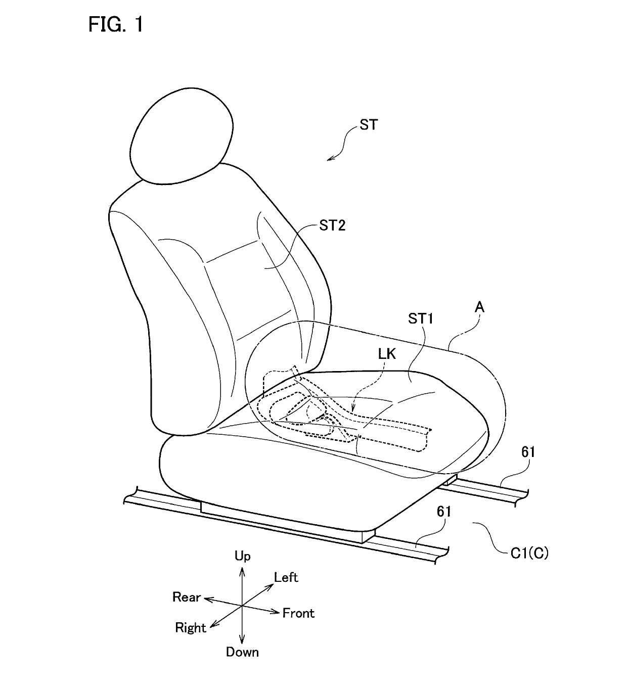
[0023]Schematic configurations of a seat lifter structure LK and a seat ST, which are practical examples of a seat lifter structure and a vehicle seat equipped with the same according to an embodiment of the present invention, will be explained with reference to FIG. 1.

[0024]FIG. 1 is an outward appearance perspective view of the seat ST. In the following explanation, respective directions of front, rear, left, right, up and down will be defined based on a state in which the seat ST is mounted on a vehicle body C, by arrows shown in FIG. 1. A left and right direction will also be referred to as a width direction.

[0025]As shown in FIG. 1, the seat ST has a cushion seat ST1 and a seat back ST2.

[0026]The seat ST is attached to be capable of moving in a front and rear direction by a known sliding structure, with respect to a pair of rails 61, 61 as fixing members installed on a floor surface C1 of the vehicle body C of the vehicle.

[0027]The seat ST has the seat lifter structure LK for e...


PUM


Abstract

A seat lifter structure which can obtain a rotation of a sector with stable torques is provided. It is equipped with a sector (7) supported to be rotatable by a support member (21), arranged to be facing with a side frame (2) by being pinched and fixed by a pair of expanded portions (6a, 6b) of a tubular shaft member (6) that is supported to be rotatable by the side frame (2), and rotating along the side frame (2) at a time of raising or lowering the side frame (2); a ring shaped spacer (13) having a first ring shaped abutting surface (13da) facing with the sector (7) and having a first outer diameter (ϕ13d2), and a second ring shaped abutting surface (13ca) facing with the side frame (2) and having a second outer diameter (ϕ13c2) different from the first outer diameter (ϕ13d2), which is installed between the sector (7) and the side frame (2) with an axial line (CL6) as a center; and a biasing member (12) that biases and abuts the sector (7) to the first abutting surface (13da) and biases and abuts the side frame (2) to the second abutting surface (13ca) by biasing the sector (7) and the side frame (2) to approach.

Description

FIELD OF THE INVENTION[0001]The present invention relates to a seat lifter structure and a vehicle seat equipped with the same.BACKGROUND OF THE INVENTION[0002]As described in the Patent Document 1, in a seat lifter for raising or lowering a seat cushion that is provided on a vehicle seat, there is known a structure in which a sector is welded and fixed to a tubular shaft member inserted into bearing holes of a pair of side panels via bushings to be freely rotatable.[0003]Also, with respect to this structure, outwardly fitting a ring shaped spacer to the tubular shaft member between the sector and the side panel, while adding a structure for biasing the tubular shaft member in a direction for making the sector and the side panel to approach is also carried out to generate torques (a static torque and a dynamic torque) by sliding friction forces between the spacer and the sector and bushings, that are caused by a rotation of the sector in conjunction with a lifting operation.[0004]Pa...

Claims


Application Information

Patent Timeline
IPC IPC(8): B60N2/16
CPCB60N2/1655B60N2/1695B60N2/1615B60N2/165B60N2/168B60N2/1605B60N2/682
Inventor MIZUKOSHI, TOSHIMITSUSHIMAZU, MASAKIMISONO, TAIJIYASUI, HIROYUKIOZAWA, MOTOHIKONOVITSKY, THOMAS D
Owner HONDA MOTOR CO LTD
Why Eureka
Try Eureka