Mechanical linkage center

A mechanical, top-notch technology, applied in the direction of tailstock/top, turning equipment, toolholder accessories, etc., can solve the problems of poor stability of driving claws, complex structure, inconvenient maintenance, etc., achieve stable torque transmission and centering, reduce Cost of use, simple and reliable effect

Pending Publication Date: 2020-06-26
LIAONING ZHONGWANG MACHINERY EQUIP MFG
View PDF2 Cites 2 Cited by
  • Summary
  • Abstract
  • Description
  • Claims
  • Application Information

AI Technical Summary

Problems solved by technology

[0002] During the turning process, the traditional one-clamp-one-top form is mostly used for clamping the turned parts, which is stable and reliable. The disadvantage is that the clamping efficiency is low, and the clamping position of the chuck affects the overall one-time processability; there are also Double top and a chicken heart clip on the spindle end to transmit torque to the part and prevent machining idling. It can process the entire outer surface of the part at one time, but the processing stability is insufficient, and the use of the chicken heart clip also affects the clamping efficiency.
For this reason, technicians have carried out further research and design, and there has been a transmissible power top disclosed in CN107855546A. Connect the end face of the part to transmit torque to the part, but the pure top compresses the spring until the end face of the part abuts against the transmission teeth on the fixed drive crankset, and the centering effect is limited; there is also an end face driven top as disclosed in CN204194824U , the drive claw contacts the end face of the part to transmit torque to the part and is in a floating form, but its structure is too complicated, and the drive claw is slidably connected to the base, and the drive claw needs to transmit torque, which will cause poor stability and easy loosening of the drive claw. Disadvantages of use effect; the seat needs to be disassembled when the drive claw is replaced, which is inconvenient for maintenance

Method used


Image

  • Mechanical linkage center
  • Mechanical linkage center

Examples


Embodiment Construction

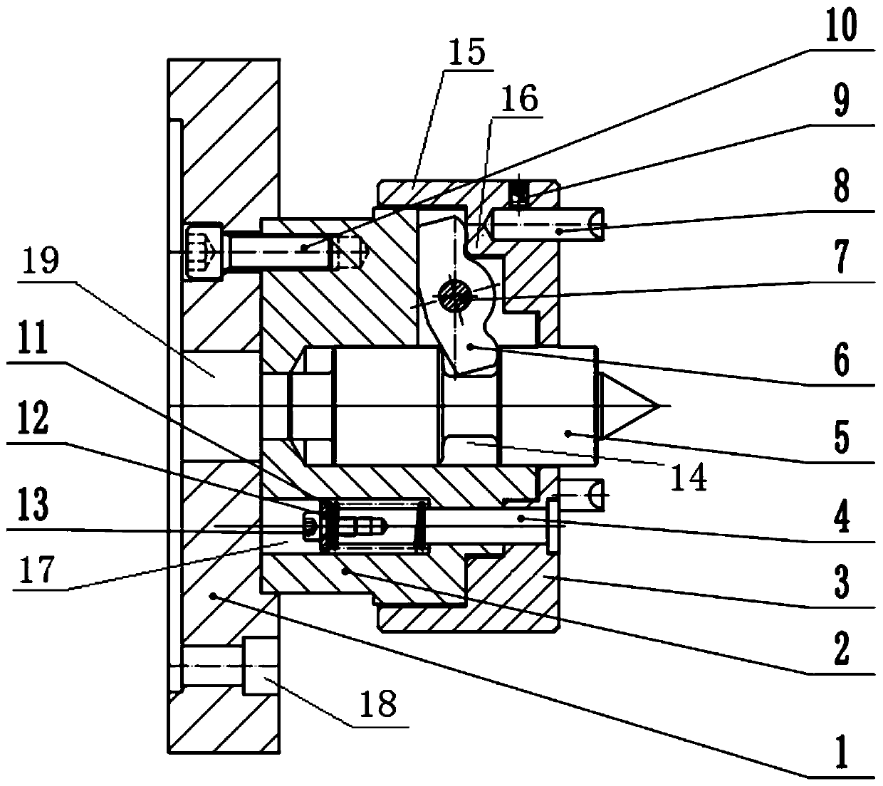
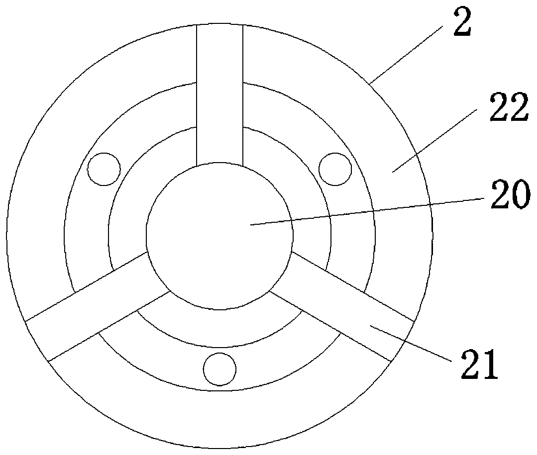
[0025] Embodiments of the present invention are described below through specific examples, and those skilled in the art can easily understand other advantages and effects of the present invention from the content disclosed in this specification. The present invention can also be implemented or applied through other different specific implementation modes, and various modifications or changes can be made to the details in this specification based on different viewpoints and applications without departing from the spirit of the present invention. It should be noted that the diagrams provided in the following embodiments are only schematically illustrating the basic concept of the present invention, and the following embodiments and the features in the embodiments can be combined with each other in the case of no conflict.

[0026] Wherein, the accompanying drawings are for illustrative purposes only, and represent only schematic diagrams, rather than physical drawings, and should...


PUM


Abstract

The invention relates to a mechanical linkage center, and belongs to the technical field of tailstocks or centers in lathes. The mechanical linkage center comprises a fixed base body. One end of the fixed base body is connected with a movable center body which can slide in the axial direction of the fixed base body. The mechanical linkage center is further provided with a slidable cover body withthe bottom up, wherein the cover body can slide in the axial direction of the fixed base body. An installation hole is formed in the fixed base body. The movable center body is arranged in the installation hole in a connected manner in a slidable manner. A through hole is formed in the slidable cover body, and the movable center body penetrates out of the through hole. The fixed base body is further provided with a lever mechanism. One end of the lever mechanism acts on the interior of an annular groove in the movable center body, and the other end of the lever mechanism acts on an inner end face of the slidable cover body, so that when the movable center body slides towards the fixed base body after being stressed with force, the movable center body drives the slidable cover body to slidein the opposite direction through the lever mechanism. A plurality of driving centers are arranged on an outer end face of the slidable cover body so that the slidable cover body can act on an end face of a part along with the opposite sliding. The mechanical linkage center is simple in structure and stable and reliable in usage, and can achieve the effect that torque transmission and centering are self-balancing in force, and thereby being reliable.

Description

technical field [0001] The invention belongs to the technical field of a tailstock or a top in a turning machine tool, in particular to a mechanical linkage top. Background technique [0002] During the turning process, the traditional one-clamp-one-top form is mostly used for clamping the turned parts, which is stable and reliable. The disadvantage is that the clamping efficiency is low, and the clamping position of the chuck affects the overall one-time processability; there are also Double tops and a chicken heart clip on the spindle end to transmit torque to the part and prevent machining idling can process the entire outer surface of the part at one time, but the processing stability is insufficient, and the use of the chicken heart clip also affects the clamping efficiency. For this reason, technicians have carried out further research and design, and there has been a transmissible power top disclosed in CN107855546A. Connect the end face of the part to transmit torqu...

Claims


Application Information

Patent Timeline
Patent Type & Authority Applications(China)
IPC IPC(8): B23B23/04
CPCB23B23/045
Inventor 彭鹏白植宋岩
Owner LIAONING ZHONGWANG MACHINERY EQUIP MFG
Why Eureka
Try Eureka