Lamination material conveying mechanism used for laminator

A technology of conveying mechanism and laminating machine, applied in the direction of layered products, lamination auxiliary operation, lamination, etc., can solve problems such as stuck rollers and maintenance, and achieve the effect of ensuring production efficiency, quiet operation and less maintenance.

Inactive Publication Date: 2016-05-11
CHONGQING HANYUAN MACHINERY
View PDF0 Cites 0 Cited by
  • Summary
  • Abstract
  • Description
  • Claims
  • Application Information

AI Technical Summary

Problems solved by technology

[0004] When using the above, it is found that the transmission guide mechanism is directly fixed on the workbench, and the produ

Method used


Image

  • Lamination material conveying mechanism used for laminator
  • Lamination material conveying mechanism used for laminator

Examples


Embodiment Construction

[0021] The present invention will be further described below in conjunction with the drawings:

[0022] The present invention will be further explained by specific examples below, but it is not intended to limit the present invention. Any modification, equivalent replacement, improvement, etc. made within the spirit and principle of the present invention shall be included in the protection scope of the present invention. .

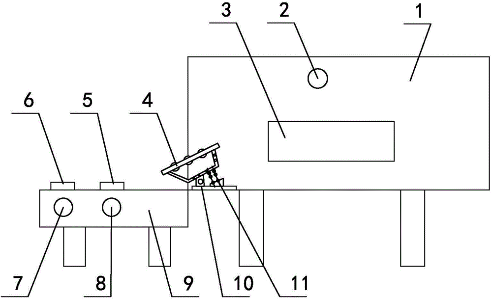
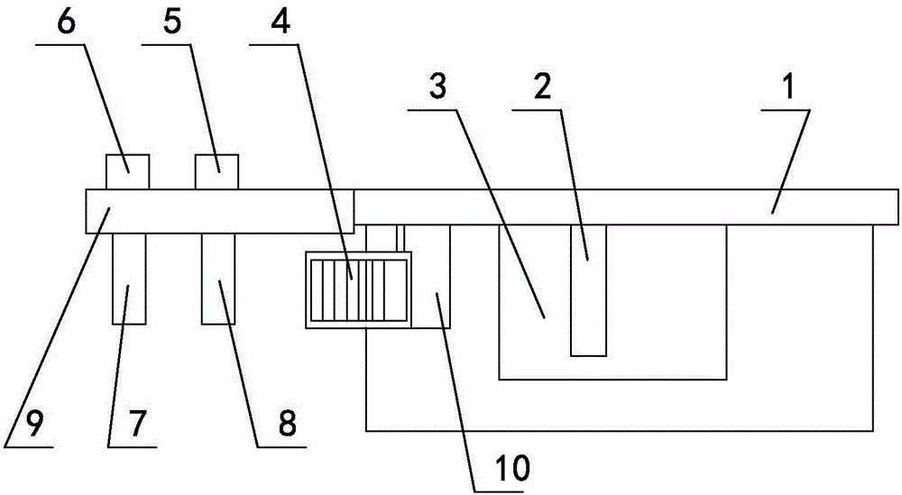
[0023] Such as figure 1 , figure 2 As shown, the placement and conveying mechanism for the laminating machine includes a workbench 1, on which a laminating machine 3 is installed, and a rotatable upper placement conveying shaft 2 is installed on the top of the workbench 1, corresponding to the laminating The machine 3 is provided with a rotatable conveying shaft 7 and a lower conveying shaft 8 on the left side of the worktable 1 from left to right. The conveying shaft 7 and the lower conveying shaft 8 are installed on the bracket 9 , A transmission guide mec...


PUM


Abstract

The invention relates to a lamination material conveying mechanism used for a laminator, and belongs to the field of technology design of laminators. The lamination material conveying mechanism comprises a workbench, the workbench is provided with a laminator, the top of the workbench is provided with a rotatable upper lamination material conveying shaft, the left side of the workbench is sequentially provided with a rotatable material-to-be-laminated conveying shaft and a lower lamination material conveying shaft corresponding to the laminator from left to right, the material-to-be-laminated conveying shaft and the lower lamination material conveying shaft are arranged on a support, a transmission guiding mechanism is arranged between the lower lamination material conveying shaft and the laminator, the transmission guiding mechanism comprises the support and an installation plate, the support is provided with a rotatable guiding roller, the left side of the support is hinged to the left side of the installing plate, the installing plate is fixedly arranged on the workbench, and a damping spring is arranged between the installing plate and the support. The lamination material conveying mechanism has the advantages of simple structure, little maintenance of the transmission guiding mechanism, little clamping of the roller, and ensuring of the production efficiency.

Description

Technical field [0001] The invention relates to a pasting conveying mechanism for a laminating machine, belonging to the technical design field of the laminating machine. Background technique [0002] At present, when the original laminating machine is in use, since there is only one placement conveying shaft, only two layers of laminating can be completed at a time when laminating and preparing glue. If you need to produce a three-layer laminated product, you cannot complete the work at one time. You can only choose one side for two-layer bonding, and then turn the semi-finished product over and perform the other side bonding, so the production efficiency is low. [0003] For this reason, an inventor designed a pasting conveying mechanism. Its structure mainly includes a worktable. A laminating machine is installed on the worktable. A rotatable upper pasting conveying shaft is installed on the top of the worktable. The left side of the worktable is provided with a rotatable mater...

Claims


Application Information

Patent Timeline
IPC IPC(8): B32B38/18
Inventor 罗昭成
Owner CHONGQING HANYUAN MACHINERY
Why Eureka
Try Eureka