
Concrete wet spraying machine chassis and concrete wet spraying machine

A concrete and wet spraying machine technology, which is applied in earthwork drilling, wellbore lining, tunnel lining, etc. It can solve the problems of wet spraying machine inoperability, poor climbing ability, large turning radius, etc., and achieve superior passability and cross-country performance , Improve stability and safety, and stabilize torque force

Pending Publication Date: 2019-02-22
CHINA RAILWAY ENGINEERING EQUIPMENT GROUP CO LTD
View PDF0 Cites 3 Cited by
  • Summary
  • Abstract
  • Description
  • Claims
  • Application Information

AI Technical Summary

Problems solved by technology

[0003] The currently used wet spraying machines are roughly divided into two types: one is a small hand-held wet spraying machine, which has defects such as poor sprayed concrete quality, loose structure, large rebound, high labor intensity, and low operating efficiency. There are many people on the surface, and serious safety accidents are prone to occur, so the development of small hand-held wet spraying machines has been gradually suppressed; the other is the wet spraying machine for automobile chassis, and the chassis of the wet spraying machine for automobile chassis Axle steering and single-axle drive have poor passability when driving on potholes and uneven roads, poor climbing ability, large turning radius, and no air compressor. For field working conditions or construction sites without air compressors, wet spraying machine will not work, limiting its scope of application

Method used


Image

  • Concrete wet spraying machine chassis and concrete wet spraying machine
  • Concrete wet spraying machine chassis and concrete wet spraying machine
  • Concrete wet spraying machine chassis and concrete wet spraying machine

Examples


Embodiment 2

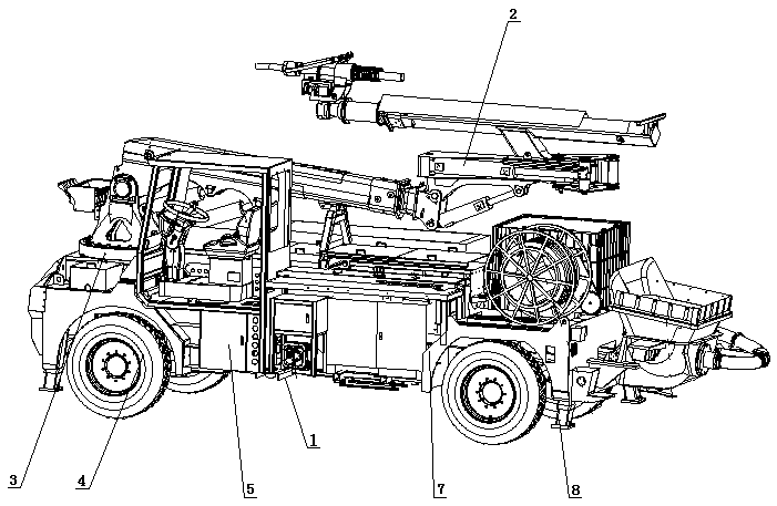
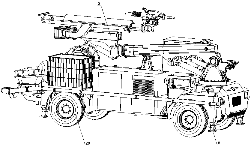
[0043] A concrete wet spraying machine, comprising a concrete wet spraying locomotive body and the concrete wet spraying machine chassis described in Embodiment 1, wherein the concrete wet spraying machine chassis is mounted on the lower part of the concrete wet spraying locomotive body;

[0044] It also includes a boom system 2, a slewing bearing 3, an air compressor and a high-pressure water pump system 5. The high-pressure water pump system 5 is installed below the vehicle frame 7, and the air compressor is installed above the vehicle frame 7. The spraying operation is performed in the case of an external air compressor. The boom system 2 is installed above the frame 7 through the slewing bearing 3, and the slewing bearing 3 drives the boom system 2 to rotate 270°. The boom in this embodiment is The system 2 includes a big arm 16, a middle arm 17 and a small arm 18. A telescopic oil cylinder is installed inside the big arm 16. The big arm 16 and the middle arm 17 are connect...


PUM


Abstract

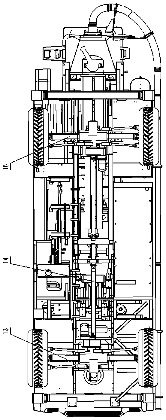
The invention relates to a concrete wet spraying machine chassis, which comprises a bearing chassis body and a travelling system. The travelling system comprises a front axle, a transmission shaft, arear axle and a hydraulic transmission system; the front axle and the rear axle are fixed to the front and rear parts of the bottom of the bearing chassis body, and connected through the transmissionshaft; the transmission shaft comprises a front transmission shaft, an intermediate transmission shaft and a rear transmission shaft; the hydraulic transmission system comprises an engine, and furthercomprises a travelling pump and a steering brake pump which are arranged on the engine, a travelling motor and an electromagnetic directional valve, the output end of the steering brake pump is connected with the electromagnetic directional valve, the electromagnetic directional valve is connected with a steering oil cylinder, the travelling pump is connected with the travelling motor in a transmission mode, the output end of the traveling motor is connected with a gearbox, the gearbox is connected with a main reducer of the front axle and the transmission shaft, and the transmission shaft isconnected with a main reducer of the rear axle. The invention further relates a concrete wet spraying machine. According to the concrete wet spraying machine chassis and the concrete wet spraying machine, the operation efficiency is high, the labor intensity is low, the passability is good, and the turning radius is small.

Description

technical field [0001] The invention relates to the field of engineering construction machinery, in particular to a concrete wet spraying machine chassis and a concrete wet spraying machine used for initial support construction of tunnel engineering, highway engineering, side slopes and the like. Background technique [0002] Concrete wet spraying machine is a kind of use of hydraulic pressure to transport the ready-mixed concrete mixture to the spray gun through the pipeline, connect the compressed air and the accelerator at the nozzle mouth to spray the mixture to the sprayed surface at a high speed, and form after rapid solidification and hardening. Construction machinery for concrete support. Shotcrete technology is widely used in various construction fields due to its simple process and economical cost. [0003] The wet spraying machines currently in use are roughly divided into two types: one is a small hand-held wet spraying machine, which has defects such as poor qu...

Claims


Application Information

Patent Timeline
IPC IPC(8): E21D11/10
CPCE21D11/10
Inventor 李魁秦宜州董恰于鹏张晓晴李宬曦王巍王占辉张豪祺盖琛
Owner CHINA RAILWAY ENGINEERING EQUIPMENT GROUP CO LTD
Learn More