Method and scanner for touch free determination of a position and 3-dimensional shape of products on a running surface

a technology of product applied in the direction of measuring devices, instruments, electrical equipment, etc., can solve the problems of uneven product distribution on the running surface, and inability to detect the position and 3-dimensional shape of products

Active Publication Date: 2019-07-30
SCHUBERT (GERHARD) GMBH
View PDF21 Cites 0 Cited by
  • Summary
  • Abstract
  • Description
  • Claims
  • Application Information

AI Technical Summary

Benefits of technology

[0029]When strips that are arranged at a distance from one another and which are advantageously arranged parallel to one another are used for optical markings, processing is particularly simple. In particular, also the gaps that are provided between the strips can be used with respect to their number, arrangement, sequence, and width for optical processing like the strips themselves.
[0055]The viewing angles of the individual cameras are thus less slanted and the distortions of the markings, in particular of the strips are less compared to scanning with a single line camera which views the image line at a much higher slant angle at the edges or which would have to be arranged much higher above the surface which, however, is much more difficult to process due to the very small angular differences of the viewing angles to the individual edges of the optical markings.

Problems solved by technology

In many industrial fields, in particular in the field of packaging, a problem exists where products that are unevenly distributed on a running surface, e.g. a conveyor belt have to be detected with respect to their positions and optionally also with respect to their height, and additionally in top view of non-circular products also with respect to their rotational position and in top view of non-rotational symmetrical products, their geometrical shapes or surface features.
Thus, due to conveyor belt contamination a contrast between product and surface may not suffice any more for precisely locating the product.
This method, however, was not suitable as a matter of principle to determine an elevation, thus, a thickness of the object.
When the surface of the product was problematic from an optical point of view, thus, glossy, reflective, little color-contrast relative to the base surface etc., this optical detection sometimes was not sufficient for position determination.
In particular it did not suffice when the reflecting surface had oriented reflective characteristics, thus, like an aluminum foil or a metal surface.
However, the pattern is ambivalent due to its repeat structure.
Therefore, the method is not suitable for moving scenes.
Furthermore, this method requires an environment that is as dark as possible and still apparent edges in the strips cannot always be differentiated from real object edges.
Strongly structured surfaces and finely structured surfaces are hardly detectable through this method, and surfaces with inferior optical properties, e.g. reflection are also hardly detectable.
Even when this method is applicable, it is hardly being used on an industrial scale due to its high level of complexity, but it is rather being used in the research, like e.g. in astronomy.

Method used


Image

  • Method and scanner for touch free determination of a position and 3-dimensional shape of products on a running surface
  • Method and scanner for touch free determination of a position and 3-dimensional shape of products on a running surface
  • Method and scanner for touch free determination of a position and 3-dimensional shape of products on a running surface

Examples


embodiments

[0058]Embodiments according to the invention are subsequently described in more detail, wherein

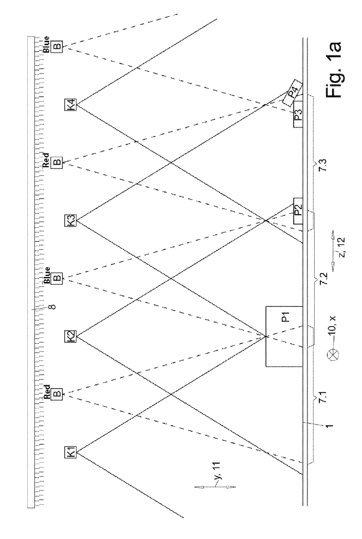
[0059]FIG. 1a: illustrates the scanner viewed in running direction of the surface;

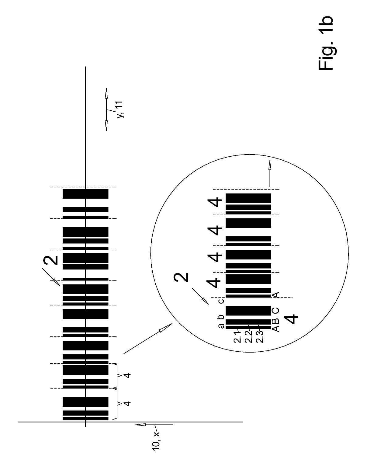
[0060]FIG. 1b: illustrates a top view of the surface with a pattern radiated on;

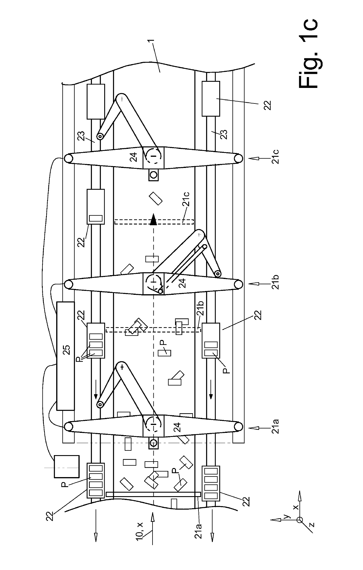
[0061]FIG. 1c: illustrates a typical application of the device according to the invention;

[0062]FIG. 2: illustrates a detail of FIG. 1a with a differently shaped product;

[0063]FIG. 3a: illustrates a strip image of a vertical lateral surface of a product; and

[0064]FIG. 3b: illustrates a strip image for a convex cambered product.

[0065]FIG. 1c illustrates a typical application for the line scanner 20 according to the invention.

[0066]This is a top view of a so-called picker line which delivers unevenly distributed products through a transport band 1 moving in running direction X, 10 wherein the products are individually gripped by pickers 21a, b, c arranged in sequence above the transport band 1 in operating direction, and wherein the...


PUM


Abstract

Line scanning of a radiated and defined strip pattern (2) facilitates determining a position of an edge of each strip (5) by taking images of the line pattern (2) from a different viewing angle and determining an elevation profile along an image line (3) therefrom and by concatenating determining the 3-D elevation profile over a surface (1).

Description

I. FIELD OF THE INVENTION[0001]The invention relates to optical detection methods for determining a 3-dimensional shape.II. BACKGROUND OF THE INVENTION[0002]In many industrial fields, in particular in the field of packaging, a problem exists where products that are unevenly distributed on a running surface, e.g. a conveyor belt have to be detected with respect to their positions and optionally also with respect to their height, and additionally in top view of non-circular products also with respect to their rotational position and in top view of non-rotational symmetrical products, their geometrical shapes or surface features. Thus, robots arranged along the conveyor belts, so-called pickers can grip the products in a controlled manner, lift them up, and e.g. place them in a box in a controlled manner.[0003]So far this was performed through an incident light line scanner that runs in lines transversal over the width of the surface wherein the line scanner takes line-shaped pictures ...

Claims


Application Information

Patent Timeline
Patent Type & Authority Patents(United States)
IPC IPC(8): G01B11/06G01B11/25H04N13/204
CPCG01B11/0691G01B11/25G01B11/0608H04N13/204
Inventor SCHINNER, KARL-LUDWIGNASRAOUI, ABDELMALEK
Owner SCHUBERT (GERHARD) GMBH
Why Eureka
Try Eureka