Method of annealing metal member
a metal member and metal technology, applied in the field of metal member annealing, can solve the problems of poor productivity of laminated core annealing, lack of specific heating method in patent document 3, and difficulty in uniformly bringing electrodes into contact with laminated core, so as to reduce the time required for heating, improve productivity, and maintain the effect of removing the strain occurring in the teeth
- Summary
- Abstract
- Description
- Claims
- Application Information
AI Technical Summary
Benefits of technology
Problems solved by technology
Method used
Image
Examples
first embodiment
(First Embodiment)
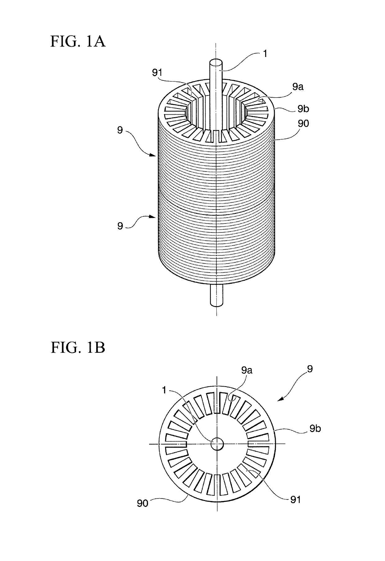
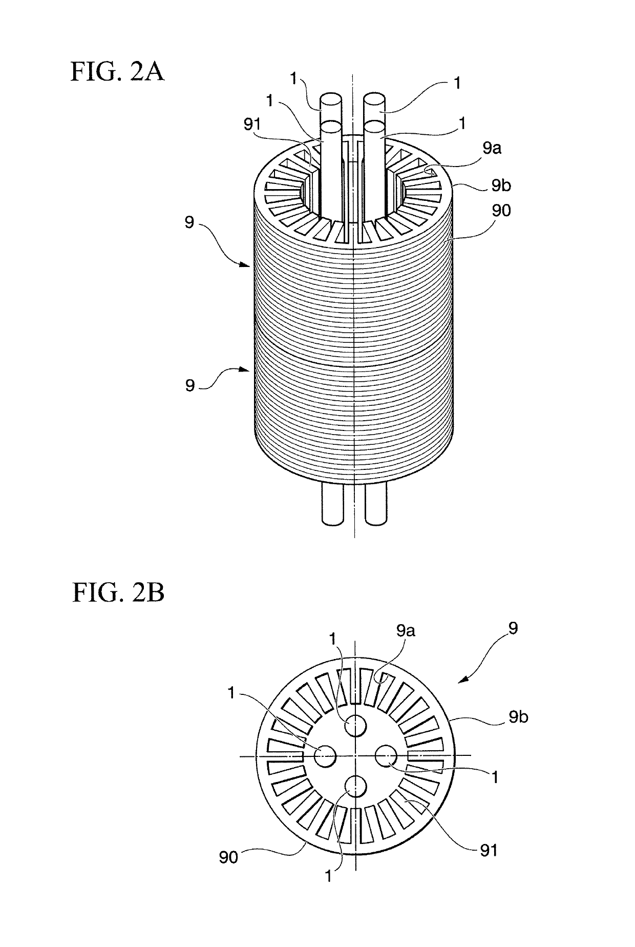
[0040]FIG. 1A and FIG. 2A are perspective views each schematically illustrating a method of annealing a laminated core according to a first embodiment. FIG. 1B and FIG. 2B are plan views each schematically illustrating a method of annealing a laminated core according to the first embodiment.
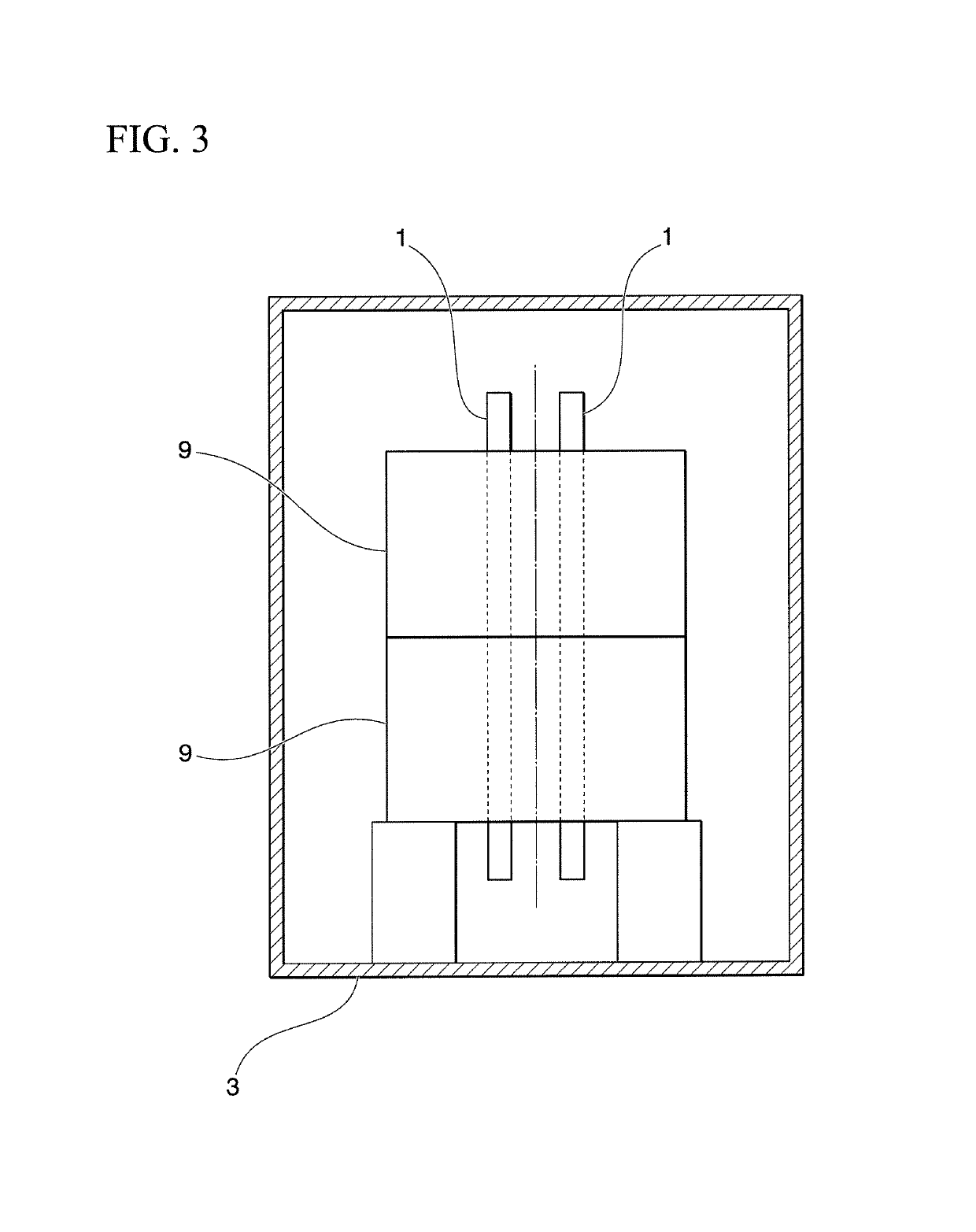
[0041]The method of annealing a laminated core according to the first embodiment is capable of annealing a laminated core 9 having a conventional general configuration. The configuration of the laminated core 9 will be briefly described below. The laminated core 9 is formed by laminating electromagnetic steel sheets 90 that have been punched into a predetermined shape, and has a hollow cylindrical shape as a whole. The laminated core 9 has an inner peripheral surface 9a having teeth 91 formed thereon. The teeth 91 are each configured so as to protrude toward the center in the radial direction, and are arranged in the circumferential direction so as to be spaced away from each ot...
second embodiment
(Second Embodiment)
[0056]Next, a second embodiment according to the present invention will be described. Note that the configuration common to that of the first embodiment will not be described. FIG. 4A is a perspective view schematically illustrating a method of annealing a laminated core according to the second embodiment. FIG. 4B is a plan view schematically illustrating a method of annealing a laminated core according to the second embodiment.
[0057]As illustrated in FIG. 4A and FIG. 4B, the first heaters 1 are inserted in the inner space of the laminated core 9, and are disposed so as to be brought close to the teeth 91. Further, a first separator 2a is provided between the first heaters 1. The first separator 2a has a function of blocking the infrared light coming from the adjacent first heaters 1 in a manner such that the first heaters 1 do not directly radiate the infrared light onto each other. Further, the first separator 2a also has a function of reflecting the infrared li...
third embodiment
(Third Embodiment)
[0062]Next, a third embodiment according to the present invention will be described. Note that the configuration common to that of the first embodiment will not be described. FIG. 5A is a perspective view schematically illustrating a method of annealing a laminated core according to the third embodiment. FIG. 5B is a plan view schematically illustrating a method of annealing a laminated core according to the third embodiment.
[0063]As illustrated in FIG. 5A and FIG. 5B, in the third embodiment, the first heaters 1 are inserted in the inner space of the laminated core 9, and are disposed between the teeth 91 formed on the inner peripheral surface 9a of the laminated core 9. Further, the laminated core 9 is heated from the inner space by the first heaters 1 disposed between the teeth 91.
[0064]According to the third embodiment, it is possible to bring the first heaters 1 close to the surface of the teeth 91 formed on the inner peripheral surface 9a of the laminated cor...
PUM
| Property | Measurement | Unit |
|---|---|---|
| wavelength bandwidth | aaaaa | aaaaa |
| temperature | aaaaa | aaaaa |
| temperature | aaaaa | aaaaa |
Abstract
Description
Claims
Application Information
 - R&D
- Intellectual Property
- Life Sciences
- Materials
- Tech Scout
- Unparalleled Data Quality
- Higher Quality Content
- 60% Fewer Hallucinations
Browse by: Latest US Patents, China's latest patents, Technical Efficacy Thesaurus, Application Domain, Technology Topic, Popular Technical Reports.
© 2025 PatSnap. All rights reserved.Legal|Privacy policy|Modern Slavery Act Transparency Statement|Sitemap|About US| Contact US: help@patsnap.com


