Supercharge Your Innovation With Domain-Expert AI Agents!

Construction machine

a construction machine and a technology for reducing the speed of attachment, applied in mechanical machines/dredgers, analogue processes for specific applications, instruments, etc., can solve the problems of limited attachment speed and inability to place this object, and achieve the effect of restricting the speed of attachmen

Active Publication Date: 2019-08-06
KOBELCO CONSTR MASCH CO LTD
View PDF13 Cites 1 Cited by
  • Summary
  • Abstract
  • Description
  • Claims
  • Application Information

AI Technical Summary

Benefits of technology

Ensures reliable prevention of attachment-cab contact while maintaining attachment speed, enhancing operational efficiency by narrowing the speed restriction area and ensuring accurate detection.

Problems solved by technology

However, the posture detector specifies the distal end position of the attachment on the basis of the angles of the boom and the arm, and for example, in the case where an object held by the attachment protrudes on a cab side from the distal end position of the attachment, the position of this object cannot be specified.
Therefore, there is a problem that even in a state where the attachment is sufficiently apart from the cab, the speed of the attachment is limited in order to accurately detect a distance from the cab to the attachment.

Method used


Image

  • Construction machine
  • Construction machine
  • Construction machine

Examples


first embodiment (

FIGS. 1 to 5)

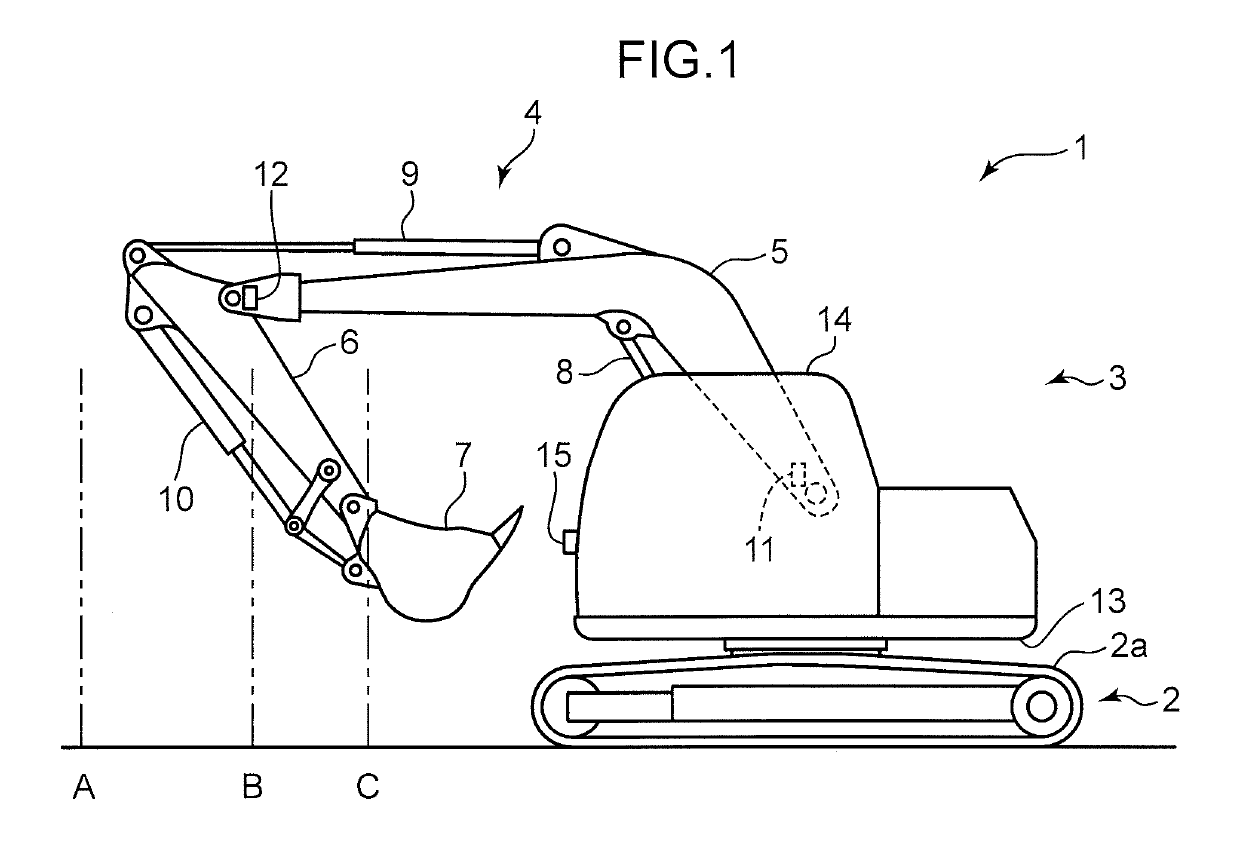
[0024]Referring to FIG. 1, a construction machine 1 as one example of a construction machine according to a first embodiment of the present invention includes a lower propelling body 2 having a crawler 2a, an upper stewing body 3 provided turnably on the lower propelling body 2, and an attachment 4 attached to the upper slewing body 3. The lower propelling body 2 and the upper slewing body 3 configure a machine body in which an operation room is defined (formed) by a cab 14 described later.

[0025]The attachment 4 has a boom 5 having a base end portion attached rotatably around an axis along a horizontal direction with respect to the upper slewing body 3, an arm 6 having a base end portion attached rotatably around an axis along the horizontal direction with respect to a distal end portion of the boom 5, and a bucket 7 attached to rotatably around an axis along the horizontal direction with respect to a distal end portion of the arm 6.

[0026]Moreover, the attachment 4 incl...

second embodiment (

FIGS. 6 and 7)

[0079]While the attachment 4 having the bucket 7 for digging has been described in the first embodiment, the attachment 4 may have a holding portion capable of holding an object to be held such as a metal piece and the like.

[0080]The construction machine 1 according to a second embodiment includes a lifting magnet (a holding portion) 33 provided in the distal end portion of the arm 6, a power storage apparatus 35 configured to store a power to be supplied to a coil (outside the figure) provided in the lifting magnet 33, and excitation manipulation unit (command output unit) 34 for outputting a holding command to excite the lifting magnet 33 using the power of the power storage apparatus 35.

[0081]The controller 32 (refer to FIG. 2) is electrically connected to the lifting magnet 33, the excitation manipulation unit 34, and the power storage apparatus 35 to supply the power of the power storage apparatus 35 to the coil of the lifting magnet 33 in accordance with the hold...


PUM


Abstract

When it is confirmed that a distal end portion of an attachment has reached a predetermined distance detection start position apart from a cab on the basis of a posture of the attachment detected by posture detector, a control apparatus determines whether or not an object to be detected has reached a predetermined stop position closer to the cab than the distance detection start position on the basis of a distance of the object to be detected by a distance detection sensor, and controls the drive unit so as to stop the attachment when determining that the object to be detected has reached the stop position, and the control apparatus controls the drive unit so that the speed of the distal end portion of the attachment becomes a predetermined target speed or lower when the distal end portion of the attachment reaches the distance detection start position.

Description

FIELD OF THE INVENTION[0001]The present invention relates to a construction machine having a machine body formed with an operation room, and an attachment attached to the machine body in a displaceable manner, and configured to prevent interference between the operation room and the attachment.DESCRIPTION OF RELATED ART[0002]Conventionally, there has been known a construction machine including a machine body formed with an operation room, an attachment attached to the machine body, drive unit for driving the attachment, posture detector for detecting a posture of the attachment, and a control apparatus configured to control the drive unit so as to prevent interface between the attachment and the operation room.[0003]The attachment has a boom having a base end portion rotatably attached to the machine body, an arm having a base end portion rotatably attached to a distal end portion of the boom, and a bucket rotatably attached to a distal end portion of the arm.[0004]The drive unit ha...

Claims


Application Information

Patent Timeline
Patent Type & Authority Patents(United States)
IPC IPC(8): G06G7/70E02F9/20E02F3/43E02F9/24E02F3/96G06G7/00G06G7/76G08B21/00B66C1/04E02F3/32B66C13/30
CPCE02F9/2033E02F3/43E02F3/435E02F9/24E02F3/963E02F3/32B66C1/04
Inventor YAMASHITA, KOJI
Owner KOBELCO CONSTR MASCH CO LTD
Features
  • R&D
  • Intellectual Property
  • Life Sciences
  • Materials
  • Tech Scout
  • Unparalleled Data Quality
  • Higher Quality Content
  • 60% Fewer Hallucinations
Learn More