Method for estimating service life of motor, motor control system, blower system, and multicopter system

a technology for motors and control systems, applied in the direction of electric motor speed/torque regulation, thermometers using value differences, instruments, etc., can solve the problem of not being able to estimate and achieve the effect of accurately estimating the service life of motors

Inactive Publication Date: 2019-08-06
NIDEC CORP
View PDF11 Cites 64 Cited by
  • Summary
  • Abstract
  • Description
  • Claims
  • Application Information

AI Technical Summary

Benefits of technology

[0016]According to the exemplary method for estimating a service life of a motor, motor control system, blower system, and multi-copter system according to aspects of the present disclosure, it is possible to accurately estimate the service life of the motor in a use condition in which the rotational speed thereof is changed.

Problems solved by technology

Therefore, it is not possible to estimate the service life of a motor with high accuracy in a use condition in which the rotational speed thereof is changed.

Method used


Image

  • Method for estimating service life of motor, motor control system, blower system, and multicopter system
  • Method for estimating service life of motor, motor control system, blower system, and multicopter system
  • Method for estimating service life of motor, motor control system, blower system, and multicopter system

Examples


first embodiment

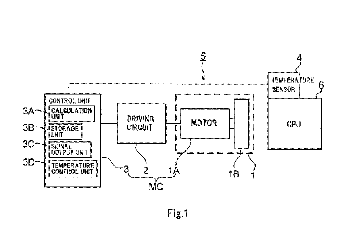
[0030]FIG. 1 is a block diagram illustrating a schematic configuration of a blower system 5 according to the present disclosure. The blower system 5 illustrated in FIG. 1 includes a blower 1, a driving circuit 2, a control unit 3, and a temperature sensor 4. The blower system 5 cools a CPU 6, which is a heat source as an example of an external apparatus. The blower system 5 and the CPU 6 are included in a personal computer (PC), for example.

[0031]The blower 1 includes a motor 1A and an impeller 1B. The motor 1A is configured by a brushless direct current (DC) motor. The motor 1A is, for example, a three-phase motor (U phase, V phase, W phase). The motor 1A includes a stator and a rotor (none of which are illustrated). The stator includes a coil that is wound around a stator core. When current flows in the coil, a magnetic field is generated, and thereby the rotor relatively rotates with respect to the stator. That is, the rotor serves as a rotation unit.

[0032]The impeller 1B is fixe...

second embodiment

[0081]FIG. 7 illustrates a schematic perspective view of the appearance of a multi-copter main body 10 according to a The multi-copter main body 10 includes a main body part 100, a first motor 101A, a second motor 101B, a third motor 101C, a fourth motor 101D, a first propeller 102A, a second propeller 102B, a third propeller 102C, and a fourth propeller 102D.

[0082]The main body part 100 has a shape that branches from the center in four directions and arms 100A to 100D. The arms 100A to 100D respectively have the first motor 101A, the second motor 101B, the third motor 101C, and the fourth motor 101D at the respective leading ends. The first motor 101A to the fourth motor 101D respectively include motors on which the first propeller 102A to the fourth propeller 102D are fixed. That is, in the multi-copter main body 10, four propellers are rotated by four motors. Note that the number of the motors and the propellers is not limited to four and may be any number larger than 1.

[0083]FI...


PUM

PropertyMeasurementUnit
temperatureaaaaaaaaaa

Abstract

A method for estimating a service life of a motor that is driven by variable duty cycle control. The method includes calculating an elapsed service life ratio representing a ratio of an elapsed service life to all service life according to the following formula to estimate the service life of the motor:Ls=∑i⁢⁢(tiLi×(1.5)m)⁢⁢m=40-max⁡(40,Ki)10,where Ls represents the elapsed service life ratio, ti represents a driving time in a section i, Li represents a service life expectancy at a duty cycle Di in the section i and at an environmental temperature of the motor being 40° C., and Ki represents a temperature in the section i.

Description

CROSS REFERENCE TO RELATED APPLICATIONS[0001]This application claims the benefit of priority to Japanese Patent Application No. 2016-253478 filed on Dec. 27, 2016. The entire contents of this application are hereby incorporated herein by reference.BACKGROUND OF THE INVENTION1. Field of the Invention[0002]The present disclosure relates to a method for estimating a service life of a motor.2. Description of the Related Art[0003]In the related art, motors have been installed in a variety of apparatuses, and each motor has its service life. For example, Japanese Unexamined Patent Application Publication No. 2016-71011 discloses an image forming apparatus in which a cooling fan including a fan motor is installed.[0004]The image forming apparatus according to the above Japanese Unexamined Patent Application Publication No. 2016-71011 estimates the service life of the cooling fan by the following method. A central processing unit (CPU) included in the image forming apparatus calculates the ...

Claims


Application Information

Patent Timeline
Patent Type & Authority Patents(United States)
IPC IPC(8): H02P5/68H02P27/08G01K3/10H02P5/00G01N25/00H02P29/60H02P29/40
CPCH02P29/60G01K3/10H02P29/40H02P5/00H02P27/08G01N25/00
Inventor YOKOYAMA, YUICHIROYAMAZAKI, SHOKIMATSUYAMA, JUNYA
Owner NIDEC CORP
Why Eureka
Try Eureka