Releasable zero backlash passive locking mechanism for a vehicle mounted rotary camera mast

a technology of rotary camera mast and passive locking mechanism, which is applied in the direction of rod connection, machine support, instruments, etc., can solve the problems of degrading structural integrity, adding cost and/or complexity, etc., and achieves the effect of reducing the risk of damag

Active Publication Date: 2019-08-13
GOOGLE LLC
View PDF14 Cites 2 Cited by
  • Summary
  • Abstract
  • Description
  • Claims
  • Application Information

AI Technical Summary

Benefits of technology

[0002]The technology described herein provides a locking mechanism having a stiff joint in the camera mount structure, which provides for zero backlash. The mechanism locks without user interaction and without an additional electro-mechanical device, meaning the device locks passively. The mechanism is releasable as it can be easily engaged and disengaged. This approach, which is discussed in more detail below, has several key advantages. For instance, it provides a joint that does not gap under dynamic load. This results in a higher natural frequency of the mast structure, which effectively means the assembly is more rigid than a conventional structure. Also, the joint does not require any additional action to lock. Rather, the motion of the mast moving to the fully deployed state automatically locks the joint. The joint should also be manually releasable with minimal effort. This provides an easy to use, secure and stable camera support structure that can be quickly deployed and stowed.

Problems solved by technology

This can be cumbersome, add cost and / or complexity, and degrade the structural integrity due to backlash of the mast during use.

Method used


Image

  • Releasable zero backlash passive locking mechanism for a vehicle mounted rotary camera mast
  • Releasable zero backlash passive locking mechanism for a vehicle mounted rotary camera mast
  • Releasable zero backlash passive locking mechanism for a vehicle mounted rotary camera mast

Examples


example arrangement

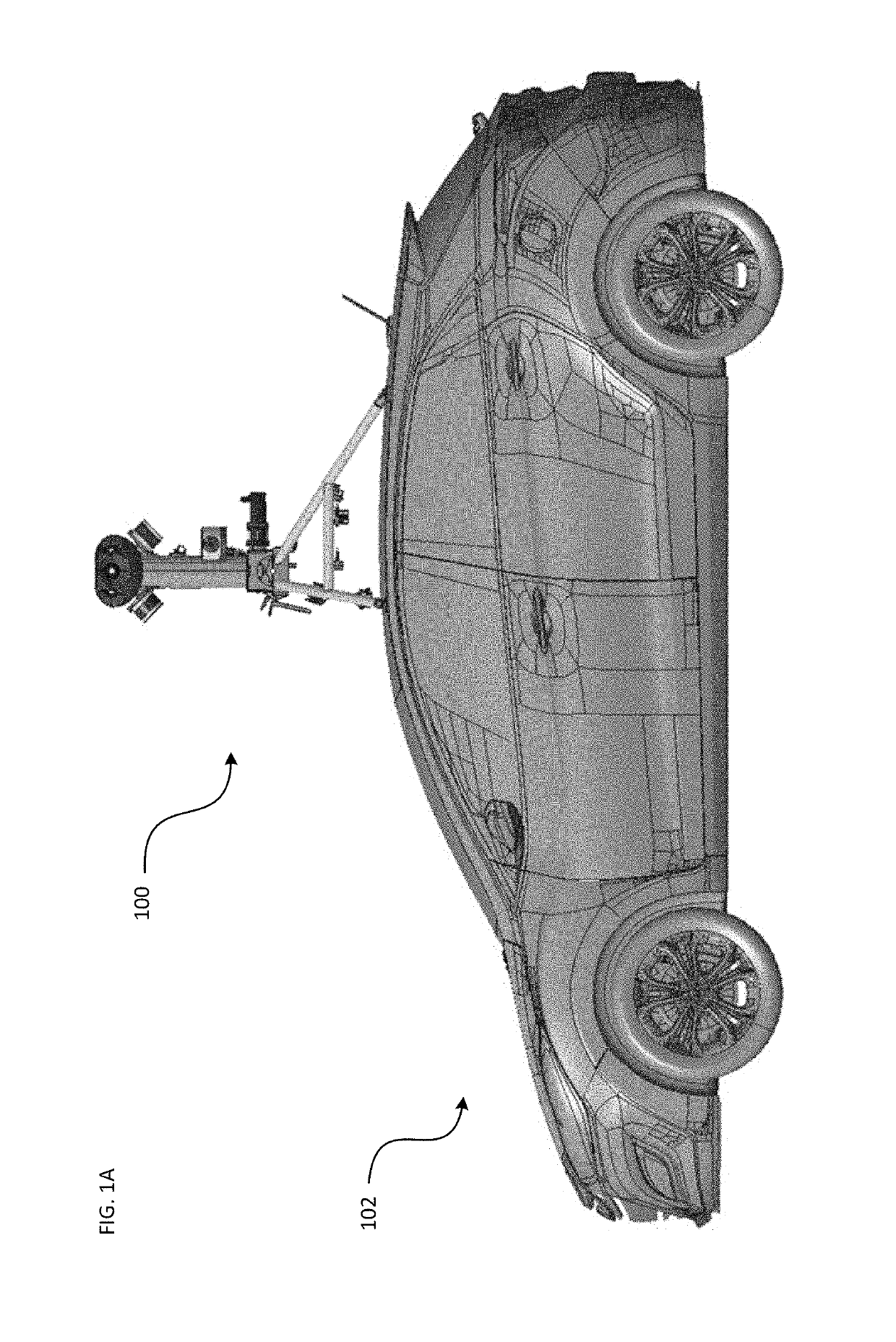
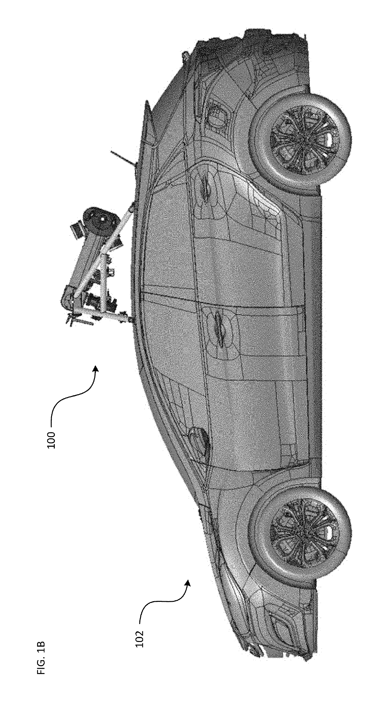
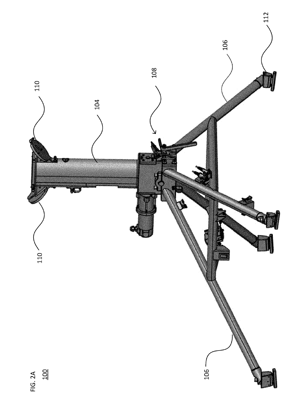
[0033]FIGS. 1A-B illustrate an example of camera mast assembly 100 in accordance with aspects of the disclosure. In particular, FIG. 1A illustrates the camera mast assembly 100 on a vehicle 102 in a deployed state, while FIG. 1B illustrates the camera mast assembly 100 in a stowed state. FIG. 2A illustrates a perspective view of the assembly 100 without the vehicle, while in the deployed state, and FIG. 2B illustrates the stand-alone assembly while in the stowed state. As shown, the assembly 100 includes a mast 104, a set of supporting frame braces 106, and a locking mechanism 108.

[0034]The mast 104 is configured to support one or more imaging devices (not illustrated in FIGS. 2A-B), which may be affixed to mounting members such as brackets 110. In one example, the imaging devices may be LIDARs. Other types of imaging devices, such as one or more cameras to generate panoramic images, may also be secured on the housing of the mast 104. As shown, the frame braces 106 may each include ...


PUM


Abstract

A rotary locking joint that has zero backlash is provided to secure a camera mast mounted on a vehicle in a deployed position. The joint is passive to lock while being easily releasable. The joint prevents rotation of the mast in one direction, with a hard stop element that prevents further rotation of the mast in the opposite direction. The locking joint includes a pawl member configured to rotate about a pawl rotation axis. The pawl member is maintained in place in the locked position via a torsion spring to ensure contact with a base portion of the mast. To release the joint, the pawl member is rotated in the opposite direction to remove a geometry interference condition. A sensor is arranged to detect whether the pawl member is in an unlocked position relative to the mast.

Description

BACKGROUND[0001]Certain applications, such as mapping and imagery for street-based panoramas, involve deploying a camera mounted on a moving vehicle. In such situations, a camera mast holding the camera is affixed to the vehicle to provide a better position and clearer lines of sight. Other components such as LIDARs may also be mounted along the camera mast. There needs to be some way to lock the mast in an upright, vertically deployed position during use. Typical latches and locking mechanisms may either allow backlash in the joint or are actively locked. Active locking may require user intervention or additional components to secure the mast in place. This can be cumbersome, add cost and / or complexity, and degrade the structural integrity due to backlash of the mast during use.BRIEF SUMMARY[0002]The technology described herein provides a locking mechanism having a stiff joint in the camera mount structure, which provides for zero backlash. The mechanism locks without user interact...

Claims


Application Information

Patent Timeline
Patent Type & Authority Patents(United States)
IPC IPC(8): B60R11/04B60R11/00F16M13/02F16M11/38
CPCB60R11/04B60R2011/004B60R2011/005F16M2200/024F16M11/38F16M13/02B60R2011/0084E04G25/08G03B17/561F16B2/185F16B7/1454F16M11/20
Inventor YERDON, MARKWAKSER, JORDAN
Owner GOOGLE LLC
Why Eureka
Try Eureka