
Actuating device with double screw connecting means

a technology of connecting means and actuating devices, which is applied in the direction of belts/chains/gears, mechanical equipment, belts/chains/gears, etc., can solve the problems of the lowest efficiency of the screw mechanism, increase the speed of the opening and closing stages, and reduce the breakaway torque

Inactive Publication Date: 2019-08-13
AB SKF
View PDF10 Cites 1 Cited by
  • Summary
  • Abstract
  • Description
  • Claims
  • Application Information

AI Technical Summary

Benefits of technology

Reduces breakaway torque and closing torque, increases speed during low-torque operations by using higher efficiency screw mechanisms when needed and lower efficiency mechanisms when forces are reduced, enhancing operational efficiency and reducing operator effort.

Problems solved by technology

The end of the valve closing run requires the maximum of exerted force but, with such an arrangement, it is the screw mechanism with the lowest efficiency that is used.

Method used


Image

  • Actuating device with double screw connecting means
  • Actuating device with double screw connecting means
  • Actuating device with double screw connecting means

Examples


Embodiment Construction

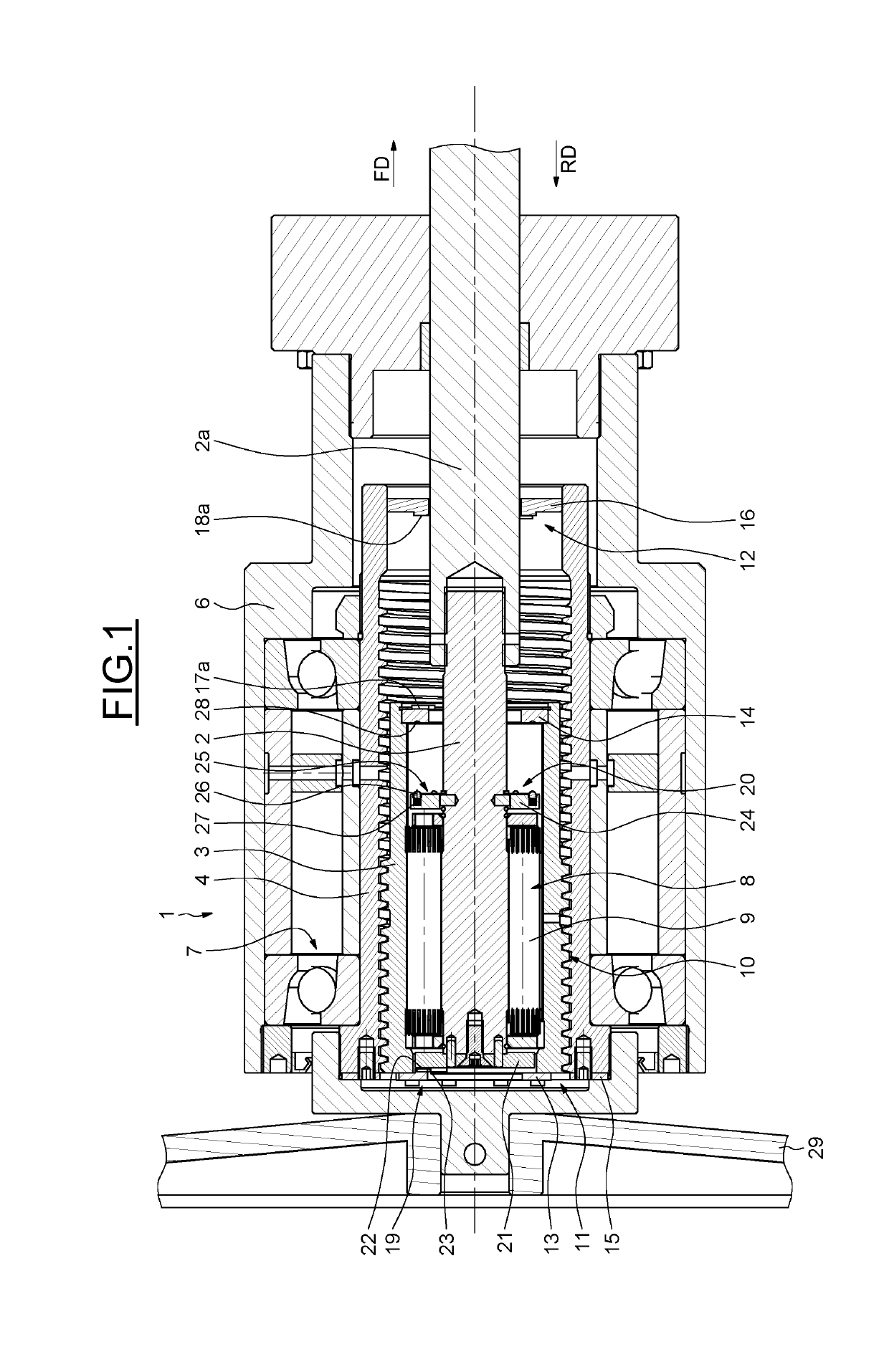
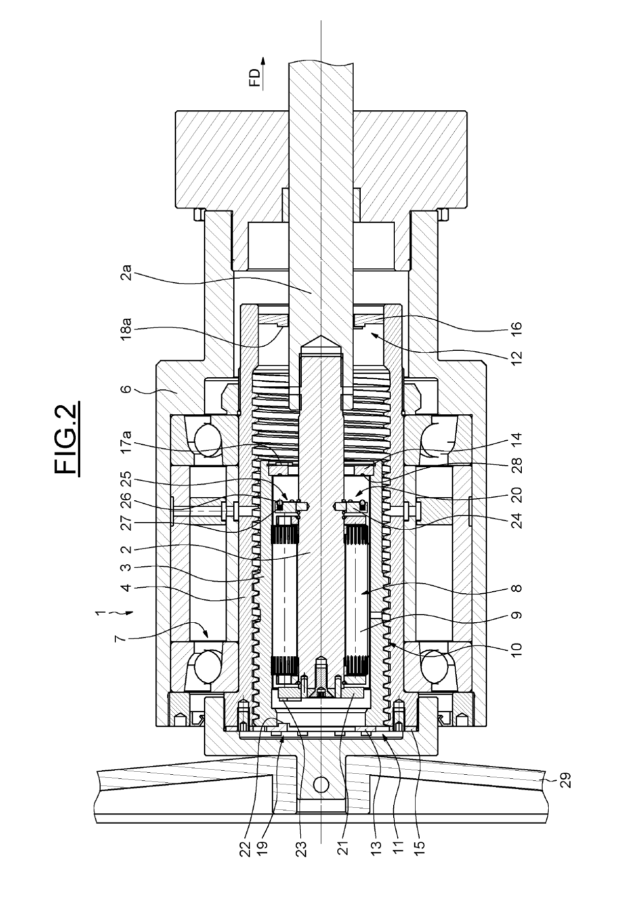
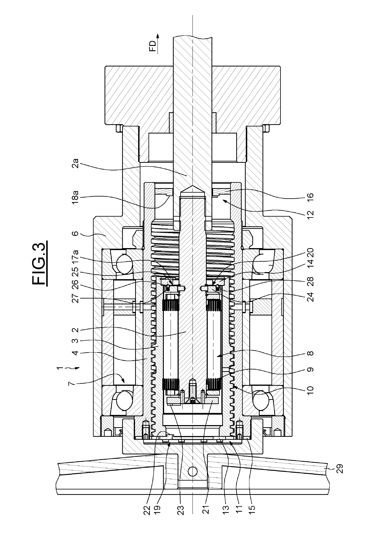
[0044]As illustrated in FIG. 1, an actuating device 1 provides a non-rotary longitudinal shaft 2 to be moved longitudinally, a rotary and translating longitudinal internal sleeve 3 disposed coaxially to and around the longitudinal shaft 2 and a non-translating and rotary longitudinal external sleeve 4 disposed coaxially to and around the internal sleeve 3.

[0045]As a reference, the longitudinal shaft 2 extends from left to right in the figures.

[0046]The longitudinal shaft 2 is connected to an organ to be moved, such as a rod 2a axially connected to an end of the shaft 2, provided with anti-rotary means (non-illustrated) for preventing rotation of the longitudinal shaft 2, such as longitudinal guiding means. As a reference, the rod 2a is attached to the right end of the shaft 2 in the FIG. 1. The rod 2a can be then connected to a translating closing plate of a knife gate valve (not shown) of a valve so as to control the flow of a fluid.

[0047]The external sleeve 4 is supported by a tub...


PUM


Abstract

An actuating device having a longitudinal shaft, an internal sleeve, an external sleeve, internal screw connecting means provided between the longitudinal shaft and the intermediate sleeve, external screw connecting means provided between the intermediate sleeve and the external sleeve. The direct efficiency of the internal screw connecting means is higher than the direct efficiency of the external screw connecting means. The self-releasable coupling means are provided between the longitudinal shaft and the internal sleeve.

Description

CROSS REFERENCE TO RELATED APPLICATIONS[0001]This is a United States National Stage Application claiming the benefit of International Application Number PCT / EP2014 / 065514 filed on Jul. 18, 2014 which is incorporated herein by reference in their entireties.FIELD OF THE INVENTION[0002]The present invention concerns actuating devices able to transform a rotation motion into a translation motion, in particular for use in gate valves; control or regulation valves or choke valves.BACKGROUND OF THE INVENTION[0003]Valves are used in a variety of industries to control the flow of fluids, in particular in the oil and gas industry. Most valves provide a valve body having a longitudinal flow bore and a transverse gate cavity that intersects the flow bore. Actuating devices are used particularly for moving a closing plate of gate cavity between a closed position, in which the plate obstructed the flow bore, and an open position, in which the plate does not obstruct the flow bore. Actuating devic...

Claims


Application Information

Patent Timeline
Patent Type & Authority Patents(United States)
IPC IPC(8): F16H25/00F16H25/20F16H25/22F16H25/24
CPCF16H25/2056F16H25/2454F16H25/2252F16H25/2015
Inventor BOCH, CHRISTIANDUBUS, JEROME
Owner AB SKF
Learn More