Detachable battery rack

a battery rack and detachable technology, applied in the field of battery racks, can solve the problems of inability to efficiently detach the battery rack, limit the choice of portable power supply, and inability to carry around, etc., to achieve convenient and efficient assembly and disassembly of the battery rack, and simple structure.

Active Publication Date: 2019-08-13
NINGBO FUTAI ELECTRIC CO LTD
View PDF5 Cites 0 Cited by
  • Summary
  • Abstract
  • Description
  • Claims
  • Application Information

AI Technical Summary

Benefits of technology

[0009]Another advantage of the invention is to provide a detachable battery rack, wherein the detachable battery rack is adapted for people to easily and efficiently assemble and disassemble members of the detachable battery.
[0010]Another advantage of the invention is to provide a detachable battery rack, wherein the detachable battery rack is able to be detachable efficiently.
[0011]Another advantage of the invention is to provide a detachable battery rack, wherein the detachable battery rack is portable to carry.
[0012]Another advantage of the invention is to provide a detachable battery rack, wherein the detachable battery rack has a simple structure and a low manufacturing cost.
[0013]Another advantage of the invention is to provide a detachable battery rack, wherein no expensive or complicated structure is required to employ in the present invention in order to achieve the above mentioned objectives.

Problems solved by technology

As a result, there is limitation on the choice of portable power supply when people use a household appliance.
What is more, people cannot use a household appliance just because that he cannot get a matched specific model of battery in certain cases.
The battery rack cannot be detachable efficiently and is not portable to carry as the battery has to be used in matching small handle household appliances.

Method used


Image

  • Detachable battery rack
  • Detachable battery rack
  • Detachable battery rack

Examples


Embodiment Construction

[0033]The following description is disclosed to enable any person skilled in the art to make and use the present invention. Preferred embodiments are provided in the following description only as examples and modifications will be apparent to those skilled in the art. The general principles defined in the following description would be applied to other embodiments, alternatives, modifications, equivalents, and applications without departing from the spirit and scope of the present invention.

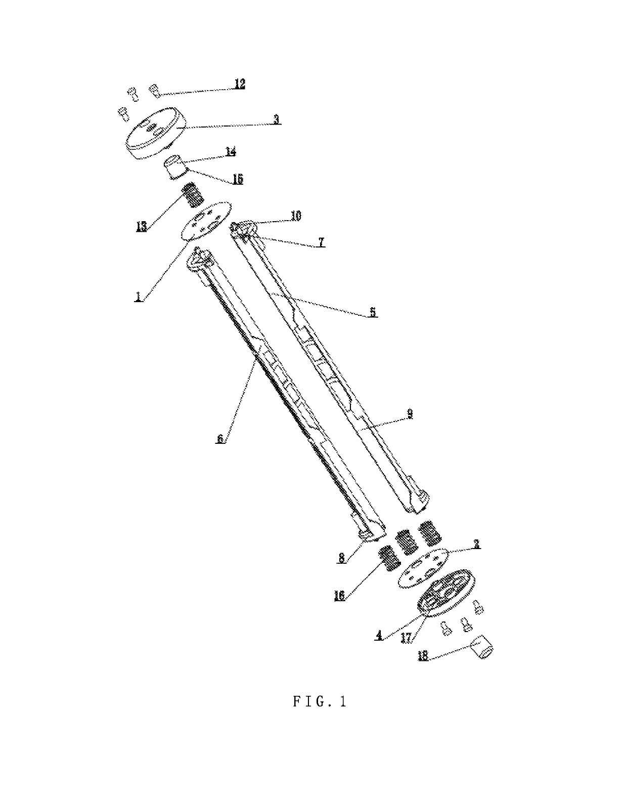
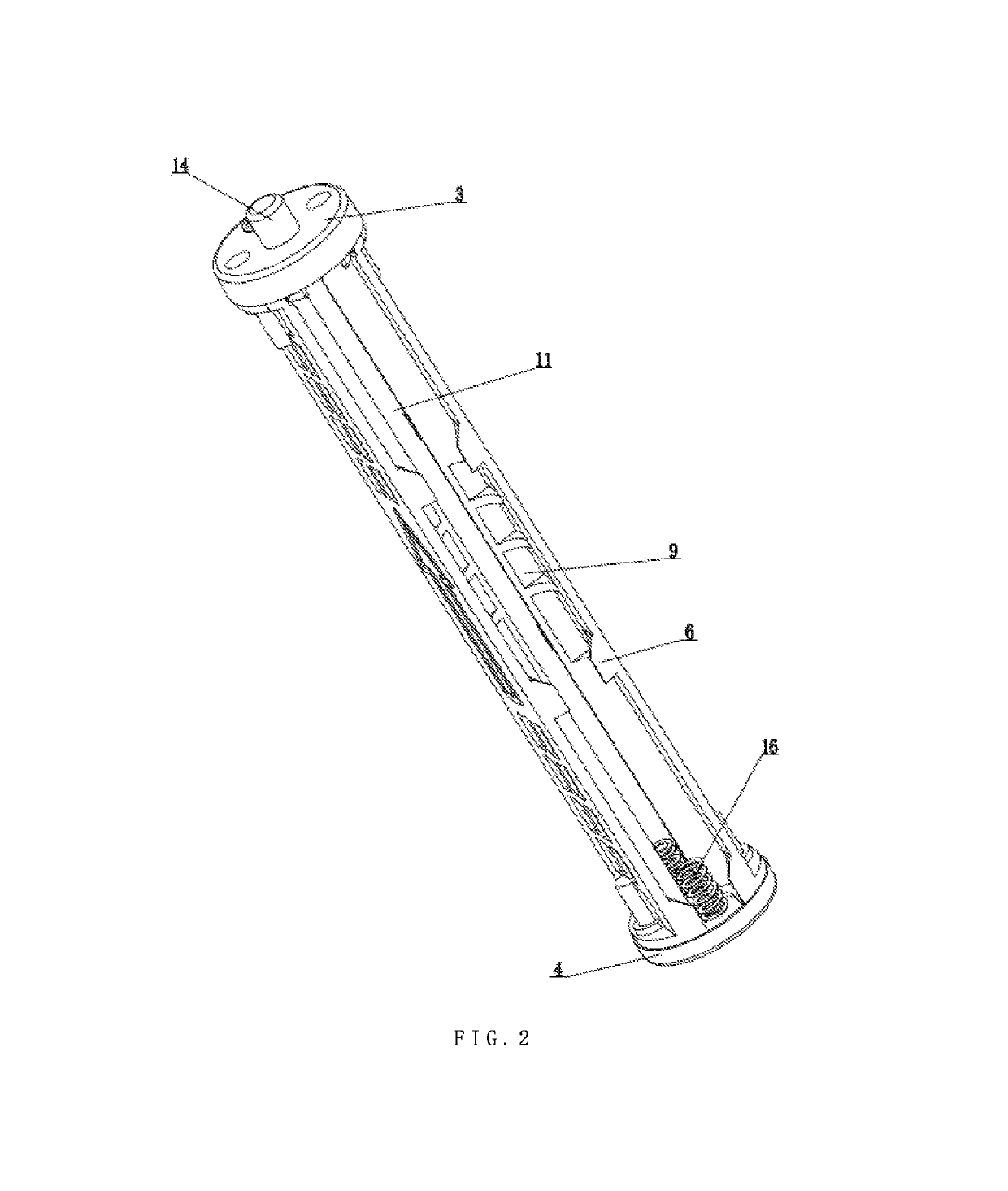
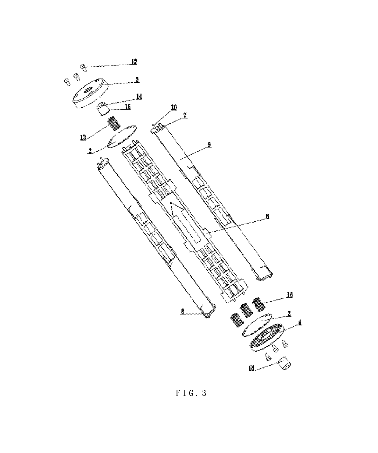
[0034]Referring to FIG. 1 to FIG. 2 of the drawings, a detachable battery rack applied to an appliance such as a flashlight according to a preferred embodiment is illustrated, in which the detachable battery rack comprises a battery compartment, an anode conductive plate 1, a cathode conductive plate 2, an anode cover 3 and a cathode cover 4. The battery compartment is formed by two compartment plates 5, each of the two compartment plates 5 further comprises an upper portion 7, a lower portion 8 ...


PUM

PropertyMeasurementUnit
conductiveaaaaaaaaaa
chemical energyaaaaaaaaaa
electrical energyaaaaaaaaaa

Abstract

A detachable battery rack includes a battery rack body, an anode end portion and a cathode end portion, wherein the battery rack body includes at least two rack panels which defines a battery cavity to install batteries, wherein the anode end portion, which is detachable mounted to the battery rack body, includes an anode conductive plate detachably coupled to the rack panels, and the cathode end portion, which is detachable mounted to the battery rack body, includes a cathode conductive plate detachably coupled to the rack panels, wherein the anode conductive plate and the cathode conductive plate are respectively provided at two opposite sides of the rack panels.

Description

BACKGROUND OF THE PRESENT INVENTION[0001]Field of Invention[0002]The present invention relates to a battery rack, and more particularly to a detachable battery rack.[0003]Description of Related Arts[0004]A battery is an electrochemical device with the ability to convert chemical energy into electrical energy. A battery, which is a container which has an accommodation space shaped like a cup, or a groove, or the accommodation space is a partial space of an another container or a composite container, is provided with inside electrolyte solutions and metal electrodes to generate electric currents. The models of batteries are various according to the size and battery capacity, such as No. 1, No. 2, No. 5, No. 7 and so on. The No. 5 (AA battery) and No. 7 (AAA battery) model of batteries are common used in daily life.[0005]Batteries are commonly used as portable power sources in household appliances, especially in small handhold appliances such as a flashlight, a lantern and so on. The b...

Claims


Application Information

Patent Timeline
Patent Type & Authority Patents(United States)
IPC IPC(8): H01M2/10H01M2/30H01M50/213H01M50/244H01M50/247H01M50/262H01M50/271H01M50/296
CPCH01M2/30H01M2/1022Y02E60/10H01M50/296H01M50/271H01M50/262H01M50/213
Inventor QIU, FUJUN
Owner NINGBO FUTAI ELECTRIC CO LTD
Why Eureka
Try Eureka